Articulated clinch joint for molded case circuit breaker

a circuit breaker and clinch joint technology, applied in the field of circuit breakers, can solve the problems of limiting the size of the internal elements, shape, configuration, material properties, etc., and achieve the effect of greater withstand valu

Active Publication Date: 2017-03-30
EATON INTELLIGENT POWER LTD
View PDF3 Cites 8 Cited by
  • Summary
  • Abstract
  • Description
  • Claims
  • Application Information

AI Technical Summary

Benefits of technology

[0008]In an exemplary embodiment, a movable contact arm assembly includes an elongated member with a distal tip, a first end, a medial portion, an actuator coupling second component, a primary pivot second component, a secondary pivot second component, a clinch joint second component, a second end, and a proximal tip. During an over-current event the movable contact arm assembly member generates a loop force. A loop force first portion is disposed on a first longitudinal side of the movable contact arm assembly member primary pivot second component, and, a loop force second portion is disposed on a second longitudinal side of the movable contact arm assembly member a primary pivot second component. In this configuration, the portions of the loop force acting on different sides of the primary pivot counteract each other thereby reducing the force acting on the movable contact arm body as well as the force transferred to the circuit breaker housing assembly. Thus, for a circuit breaker housing assembly of a selected size, the movable contact arm assembly provides a greater withstand value compared to known movable contact arm assemblies.

Problems solved by technology

This relationship is, however, limited by the size, shape, configuration, and material properties of the elements of the circuit breaker.
The size of the circuit breaker housing assembly, however, limits the increase in the size of the internal elements.

Method used


Image

  • Articulated clinch joint for molded case circuit breaker
  • Articulated clinch joint for molded case circuit breaker
  • Articulated clinch joint for molded case circuit breaker

Examples


Embodiment Construction

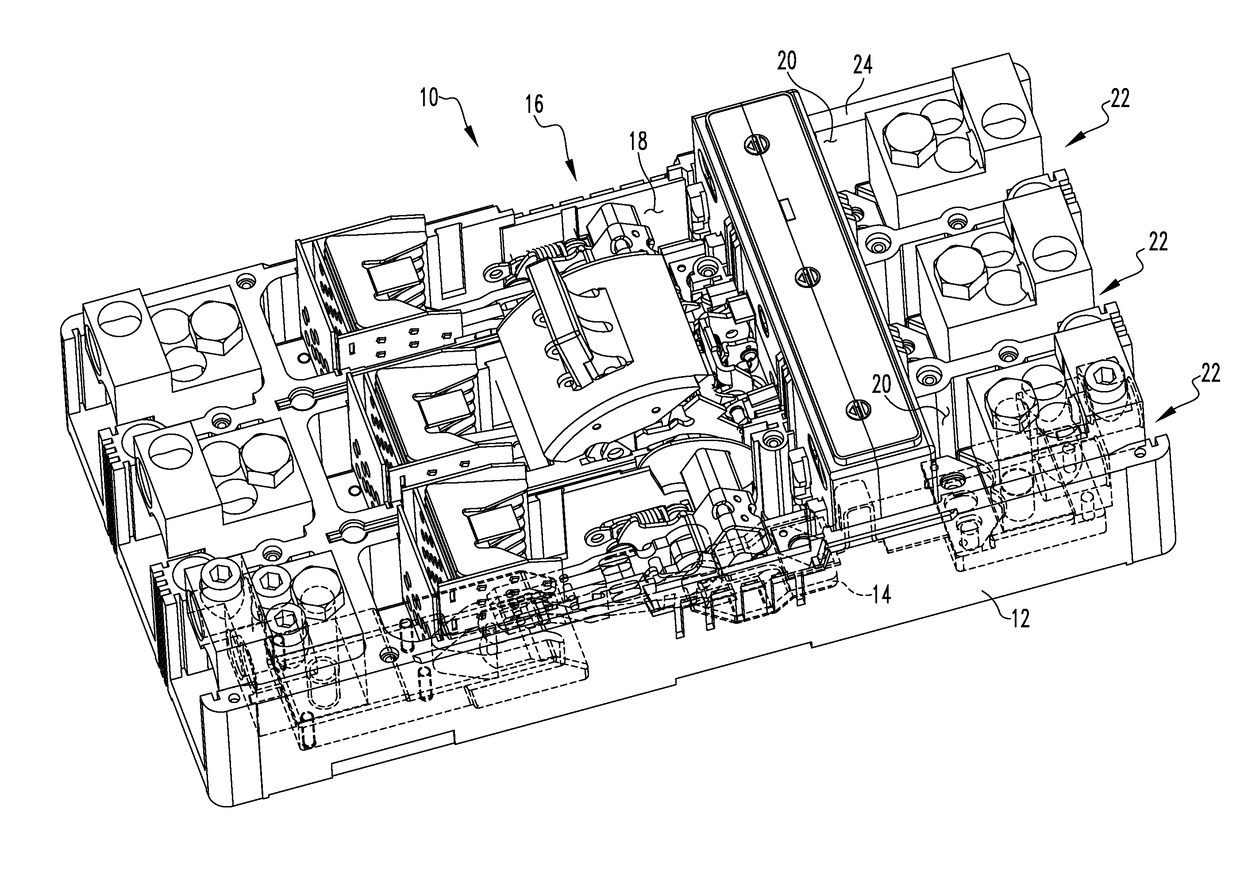
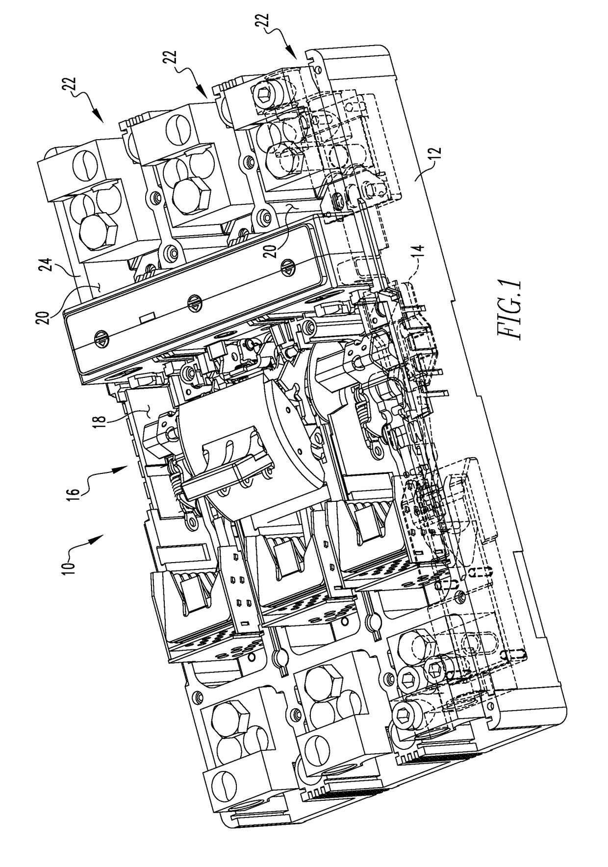
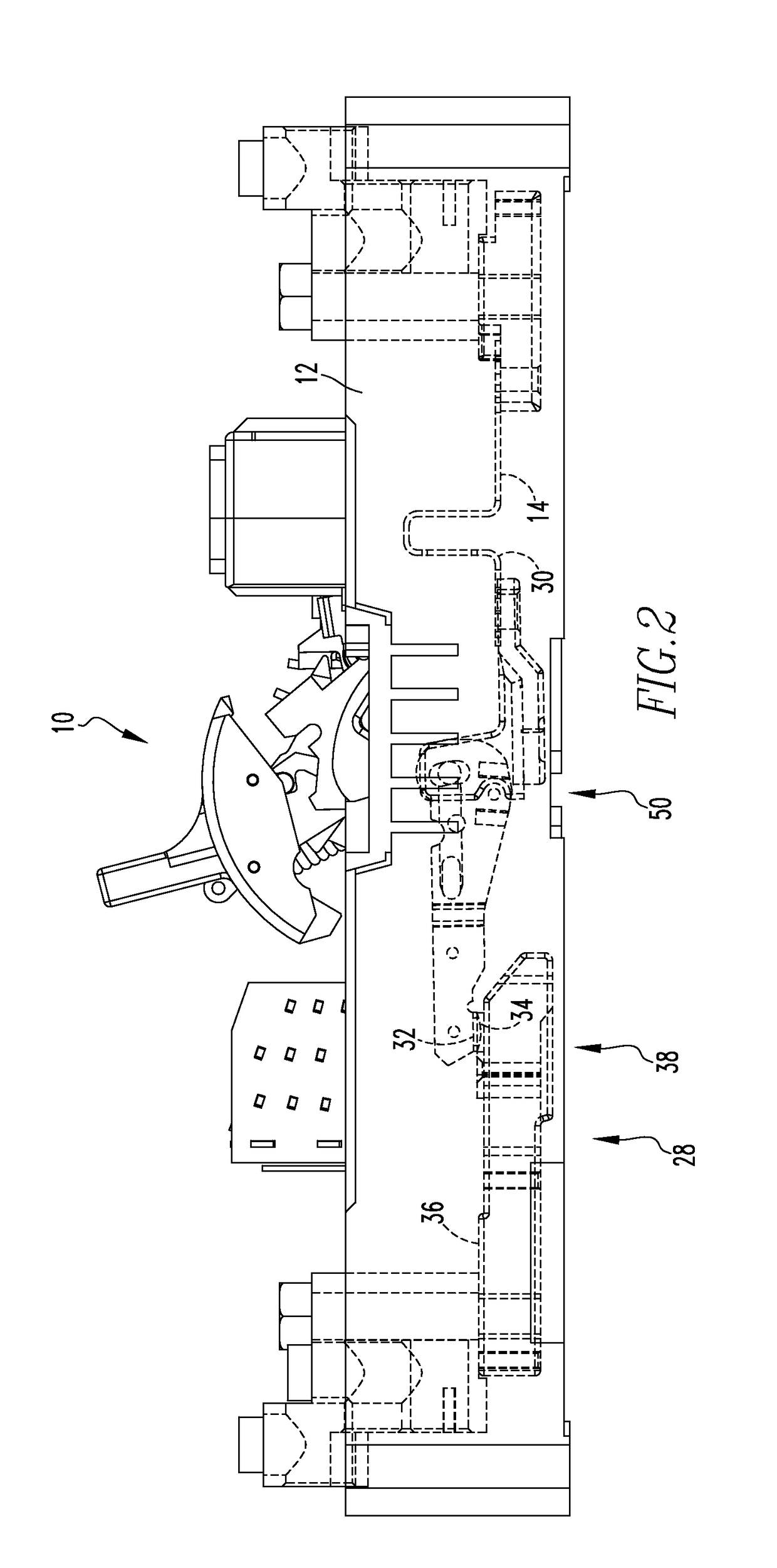
[0016]It will be appreciated that the specific elements illustrated in the figures herein and described in the following specification are simply exemplary embodiments of the disclosed concept, which are provided as non-limiting examples solely for the purpose of illustration. Therefore, specific dimensions, orientations, assembly, number of components used, embodiment configurations and other physical characteristics related to the embodiments disclosed herein are not to be considered limiting on the scope of the disclosed concept.

[0017]Directional phrases used herein, such as, for example, clockwise, counterclockwise, left, right, top, bottom, upwards, downwards and derivatives thereof, relate to the orientation of the elements shown in the drawings and are not limiting upon the claims unless expressly recited therein.

[0018]As used herein, the singular form of “a,”“an,” and “the” include plural references unless the context clearly dictates otherwise.

[0019]As used herein, a “coupl...


PUM


Abstract

A movable contact conductor assembly is provided. The movable contact arm assembly includes an elongated member with a distal tip, a first end, a medial portion, an actuator coupling second component, a primary pivot second component, a secondary pivot second component, a clinch joint second component, a second end, and a proximal tip. During an over-current event the movable contact arm assembly member generates a loop force. A loop force first portion is disposed on a first longitudinal side of the movable contact arm assembly member primary pivot second component, and, a loop force second portion is disposed on a second longitudinal side of the movable contact arm assembly member primary pivot second component.

Description

BACKGROUND OF THE INVENTION[0001]Field of the Invention[0002]The disclosed and claimed concept relates to a circuit breaker and, more specifically, to a circuit breaker operating mechanism that is structured to resist rebounding from an open, first configuration to a closed, second configuration.[0003]Background Information[0004]Electrical switching apparatus include, for example, circuit switching devices, circuit interrupters, such as circuit breakers, network protectors, contactors, motor starters, motor controllers, and other load controllers. Electrical switching apparatus such as circuit interrupters and, in particular, circuit breakers, are well known in the art. Circuit breakers are used to protect electrical circuitry from damage due to an over-current condition, such as an overload condition or a relatively high level short circuit or fault condition. Circuit breakers typically include a number of pairs of separable contacts, an operating mechanism, and a trip unit. The se...

Claims


Application Information

Patent Timeline
Patent Type & Authority Applications(United States)
IPC IPC(8): H01H71/10H01H71/02
CPCH01H71/10H01H2205/002H01H71/02H01H3/222H01H71/43H01H71/525
Inventor KOZAR, AARON THOMASSLEPIAN, ROBERT MICHAEL
Owner EATON INTELLIGENT POWER LTD
Why Eureka
Try Eureka