
Catheter Structure with Improved Support and Related Systems, Methods, and Devices

Active Publication Date: 2017-04-06
QXMEDICAL
View PDF3 Cites 7 Cited by
  • Summary
  • Abstract
  • Description
  • Claims
  • Application Information

AI Technical Summary

Benefits of technology

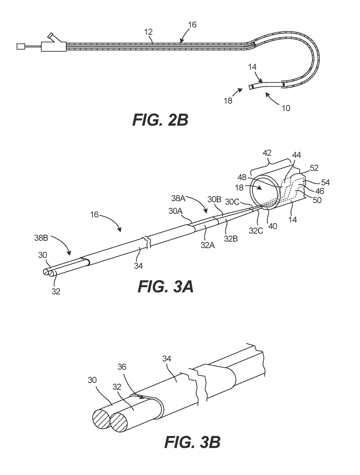
The patent describes various catheter designs that can be used with standard guiding catheters and sheaths. These catheters have a distal tube with a tubular wall and a support membrane around a portion of the tube. The support membrane can be a single elongate member or multiple elongate members. The catheter also has one or more sheath segments that are placed around the elongate members to protect them. The sheath segments can be the same length as the elongate members or different lengths. The catheter can also have a shaft lumen that is in fluid communication with the tube lumen, allowing fluid to flow through the catheter. The patent also describes various methods for accessing the blood vessel using these catheters.

Problems solved by technology

However, this transmission of torque can induce stresses on the connection between the proximal shaft and the tube, in some cases stresses that are so great that the stresses cause failure or separation of the shaft and tube at the connection point.
Thus, the torque generated at the connection point as a result of the low torsional compliance characteristics (including, for example, high torque transmission) of these devices coupled with the tensile or compressive forces generated from urging the catheter axially can cause device failures.
Many of these known catheters have proximal shafts with low torsional compliance, thus making them susceptible to the problems described above.
One disadvantage of a multi-layer catheter is the possible delamination that can occur between layers.
A result of such a delamination is that passage (especially withdrawal) of a device through the distal tip may be impaired.
Another disadvantage of a catheter having a proximal shaft coupled to a distal tube is that the typically metallic proximal or manipulation shaft may shear, delaminate, peel or disconnect from the distal tube during use.

Method used


Image

  • Catheter Structure with Improved Support and Related Systems, Methods, and Devices
  • Catheter Structure with Improved Support and Related Systems, Methods, and Devices
  • Catheter Structure with Improved Support and Related Systems, Methods, and Devices

Examples


Embodiment Construction

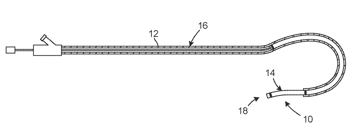
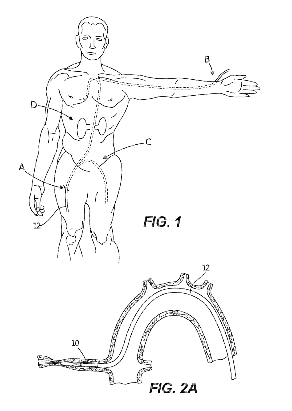
[0110]The various embodiments disclosed and contemplated herein relate to a catheter, such as an extension guide catheter, having a length or section containing a discontinuous or segmented structure. Further embodiments relate to catheters having such discontinuous or segmented structures that can be modified or varied to modify the torsional compliance characteristics of the device. Certain of these catheter embodiments can be adapted to be positioned through and extend distally from a conventional guiding catheter or sheath, wherein the guiding catheter or sheath is adapted to extend into a patient.

[0111]Further embodiments disclosed and contemplated herein relate to an improved catheter tip that can be incorporated into any known multi-layer catheter, including an extension catheter, guiding catheter, sheath, delivery catheter, or any other such catheter.

[0112]Additional embodiments disclosed and contemplated herein relate to a support layer than can be positioned around a porti...


PUM

PropertyMeasurementUnit
Lengthaaaaaaaaaa
Flow rateaaaaaaaaaa
Sizeaaaaaaaaaa

Abstract

Certain embodiments herein relate to an extension catheter for positioning through a conventional guiding catheter into the vasculature of a patient, the extension catheter having a distal tubular member and a proximal elongated shaft coupled to the distal tubular member, wherein the proximal shaft has a length or section containing at least one discontinuous or segmented structure, and further wherein such structures that can be modified or varied to modify the torsional compliance characteristics of the device. Further embodiments relate to a multi-layer catheter having a protective wrap at or near the distal end of the catheter.

Description

CROSS-REFERENCE TO RELATED APPLICATION[0001]This application claims the benefit under 35 U.S.C. §119(e) to U.S. Provisional Application 62 / 235,751, filed Oct. 1, 2015 and entitled “Catheter Structure with Improved Support and Related Systems, Methods, and Devices,” which is hereby incorporated herein by reference in its entirety.FIELD OF THE INVENTION[0002]The various embodiments disclosed herein relate to catheters for use as medical devices, including extension catheters (as defined herein) for use with guiding catheter systems, and more particularly to catheters having a length or section containing a discontinuous or segmented structure, including such structures that can be modified or varied to modify the torsional compliance characteristics of the device. Further embodiments relate to an improved catheter tip for incorporation into the various types of catheters, especially those having multi-layer tubes.BACKGROUND OF THE INVENTION[0003]The general use of catheters as medical...

Claims


Application Information

Patent Timeline
IPC IPC(8): A61M25/01A61M25/00
CPCA61M25/0147A61M25/0054A61M2025/0062A61M2025/0047A61M25/0045A61M25/0108A61M25/0662A61M2025/0004A61M2025/0175A61M25/0052
Inventor NORMAN, WILLIAMDI CAPRIO, FERNANDOPANARELLO, GIANFRANCO
Owner QXMEDICAL
Learn More