Coronary sinus access catheter with forward-imaging

a catheter and coronary sinus technology, applied in the field of coronary sinus access catheters/introducers, can solve the problems of cellular death, discontinuation of rapid heart rate, and difficulty in finding the opening, and achieve the effect of less rotation

Inactive Publication Date: 2005-01-27
OLYMPUS CORP
View PDF20 Cites 153 Cited by
  • Summary
  • Abstract
  • Description
  • Claims
  • Application Information

AI Technical Summary

Benefits of technology

[0027] The tight-radius deflection mechanism consists of one or two deflection wires pulling on a segment of the distal portion of the lead, creating deflections of about 60 degrees over the last centimeter of the catheter distal end. If two wires are used the deflection is bi-directional; one wire creates unidirectional deflections. If unidirectional deflection is used, the catheter can be torqued so that rotation on the proximal end results in a similar rotation on

Problems solved by technology

Alcohol contact results in cellular death and the discontinuation of the rapid heart rate.
With CHF patient candidates, finding the opening is much more elusive.
Pacemaker implants are performed on the right side of the heart since implants in the left heart could lead to thrombi heaving deleterious consequences such as a stroke or heart attack.
Locating the proper left-ventricular branch (where the left ventricle can be chronically paced) has been difficult in biventricular pacing clinical studies.
Finding the correct branch in these highly variable hearts has been the other major challenge in biventricular pacing.
Using the coronary sinus lead to access the proper branch was difficult due to the size of the lead and the inability to make sharp-angled bends required to access a suitable coronary sinus branch.
The complexity in the curve geometries and stiffness characteristics of the above disclosures is due to the physician relying on “touch and feel” at the proximal end of the catheter.
The difficulty with pre-curved catheters is the extreme variability of coronary sinus location and geometry in hypertrophic hearts.
As a consequence of these limitations, implantation of a coronary sinus lead significantly increases the time of pacemaker implantation.

Method used


Image

  • Coronary sinus access catheter with forward-imaging
  • Coronary sinus access catheter with forward-imaging
  • Coronary sinus access catheter with forward-imaging

Examples


Embodiment Construction

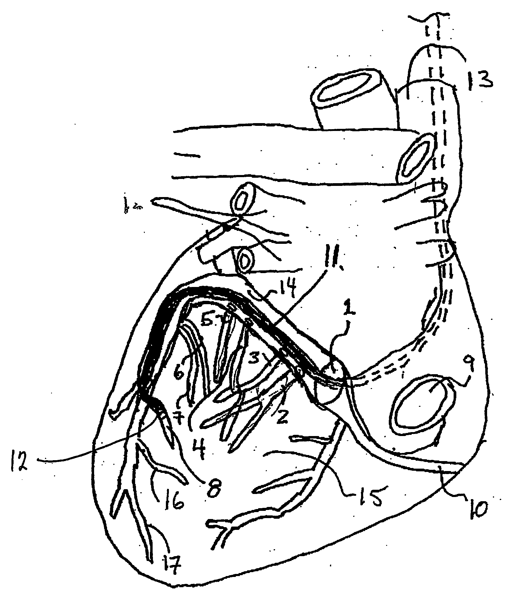
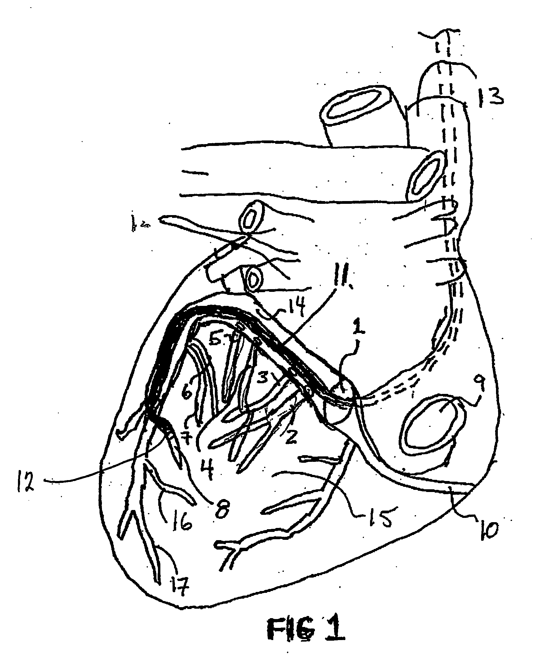
[0042]FIG. 1 shows the expected route of the catheter (11) as it is inserted onto the coronary sinus to a position in the anterior-lateral branch (8) of the coronary sinus vasculature. A sinus lead (12) is inserted through a puncture or cutdown technique into the subclavian vein where it eventually enters the superior vena cava (13). The lead is directed to the tricuspid valve plane in the lower right atrium where the os of the coronary sinus (1) is located. The os of the coronary sinus (1) is located near the tricuspid valve and the inferior vena cava (9). After entry into the coronary sinus os, the coronary sinus diverges into the great cardiac vein (14) and the right coronary vein (10). Directing the catheter (11) in the direction of the great cardiac vein (14) requires a tight radius deflection towards the left side of heart. As the catheter traverses the coronary sinus (1), several branch points called the posterior lateral coronary veins (2,3,4,5) run laterally along the left ...


PUM


Abstract

A coronary access catheter system simplifies the insertion of objects into distal branches of the coronary sinus. The system incorporates a real-time forward-imaging means to view the os and the branches of the coronary sinus. Preferably, the catheter uses near-infrared light as the forward-imaging means, but it could also include ultrasound or electromagnetic transducer. As the image is viewed, the catheter tip can be steered into the coronary sinus os and deflected in a tight radius bend on the distal end to navigate the short radius, right angle turns found in the coronary sinus branches. At that point, a flexible sheath can be placed over the guide catheter or objects such as guidewires can be inserted into channels of the guide catheter. The system consists of a catheter and image acquisition unit, which displays the forward image.

Description

[0001] This application claims the benefit of U.S. provisional patent application No. 60 / 332,654 filed on Nov. 9, 2002.BACKGROUND OF THE INVENTION [0002] 1. Field of the Invention [0003] This invention relates to cardiac catheters / introducers used to access the coronary sinus and navigate the sinus vasculature using a deflecting distal end with feedback provided by a forward-imaging means. [0004] 2. Related Art [0005] The following references provide useful information in the filed of the present invention, and are incorporated by reference herein: LurieJune 19955,423,772Adams7 / 19955433,729.JaraczewskiAugust 19955,445,148TonerFebruary 19965,488,960AvitallJuly 19975,642,736SwoyerNovember 19975,683,445RandolphJuly 19985,775,327WangMarch 20006,041,248TockmanOctober 20006,129,750AmundsonJanuary 20016,178,346LinMarch 20016,200, 269WilliamsJune 20026,408,214B1ZeylikovichAugust 20026,437,867OckulyOctober 20026,458,107B1[0006] Cardiac catheterizations are procedures in which a cardiologist...

Claims


Application Information

Patent Timeline
IPC IPC(8): A61B5/00A61B8/12
CPCA61B5/0084A61B8/12A61B5/0086
Inventor AMUNDSON, DAVIDHANLIN, H. JOHNBLACKENSHIP, LARRY
Owner OLYMPUS CORP
Why Eureka
Try Eureka