Stators for electrical machines

a technology of electrical machines and stators, which is applied in the field of rotating electrical machines, can solve the problems of difficult coil inserting into the radial slots, high degree of skill, and time-consuming winding process, and achieve the effect of increasing the rotational symmetry of the winding slots about the stator, reducing the magnitude of undesirable flux densities, and reducing the degree of skill

Active Publication Date: 2011-08-02
GE POWER CONVERSION
View PDF5 Cites 2 Cited by
  • Summary
  • Abstract
  • Description
  • Claims
  • Application Information

AI Technical Summary

Benefits of technology

[0015]It will be readily appreciated that the pre-formed coils for the stator must also have axially-extending winding runs that are substantially parallel to one another both in the axial direction of the stator and in a perpendicular direction. In other words, the winding runs do need not be angled relative to one another in order to be received in the radial slots of a conventional stator but can be made substantially parallel. Winding a stator according to the present invention may be achieved by simply and easily inserting the parallel winding runs of each pre-formed coil into the parallel winding slots of each winding slot pair. The present invention therefore provides a significant reduction in winding time and damage to the pre-formed coils is much less likely during the winding process. The stator according to the present invention is of particular benefit in large electrical machines with high numbers of poles as the pre-formed coils for such machines are inherently stiff.
[0028]The present invention is, however, particularly well suited to large electrical machines that have high numbers of poles. This is because the number of winding slots formed in the stator in an electrical machine is generally proportional to the number of poles and the mean angular separation between adjacent winding slots at the first cylindrical surface of the stator is inversely proportional to the number of slots and therefore the number of poles. This means that the more poles that an electrical machine has, the more winding slots it will have and the angular separation between those slots will be lower. This is particularly important because the amount by which each winding slot of each winding slot pair needs to be rotated from the orientation of the equivalent conventional radial slot in order for the two slots to be parallel is directly dependent upon the angular separation of the two slots. The lower the angular separation of the two winding slots the less they will need to be rotated and the easier it will be to fulfil the necessary design criteria. For example, stator teeth are much more likely to be strong and have acceptable vibration characteristics if the winding slots either side of each stator tooth are formed at only a relatively small angle to the orientation of the equivalent conventional radial slots than if the winding slots are formed at larger angles.
[0030]For example, in a stator with 240 winding slots and a three-phase single-layer stator winding it is generally preferred that each winding slot is formed at an angle of 2.25° to the orientation of the equivalent conventional radial slot and that each winding slot is rotated away from that orientation about the line of intersection between its central plane and the first cylindrical surface of the stator. This arrangement of winding slots is preferred because it enables the rotational symmetry of the winding slots about the stator to be maximised. Increased rotational symmetry is a benefit as it can minimise the magnitude of undesirable flux densities generated in the stator teeth and it enables the performance of the stator to be better predicted. Furthermore, as explained above, a high degree of rotational symmetry is sometimes necessary in order to enable the construction of stators formed from axially stacked laminations, particularly if the stator is large. Finally, at least some of the stator teeth that are formed in a stator with slots oriented in the above manner may be aligned along a radius of the stator and depending on the particular slot width, stator winding and the axial line of rotation of each of the winding slots this may lead to suitably strong teeth with acceptable vibration characteristics.

Problems solved by technology

However, the need for the axially-extending winding runs of each pre-formed coil to be formed at an angle relative to one another so that each winding run extends along a radius of the stator can make it difficult to insert the coils into the radial slots.
This means that the winding process is often time-consuming and may require a high degree of skill in order to prevent the pre-formed coils being damaged.
These problems are particularly acute in large electrical machines with a high number of poles as the pre-formed coils for such electrical machines are also large and their endwindings are inherently stiff.

Method used


Image

  • Stators for electrical machines
  • Stators for electrical machines
  • Stators for electrical machines

Examples


Embodiment Construction

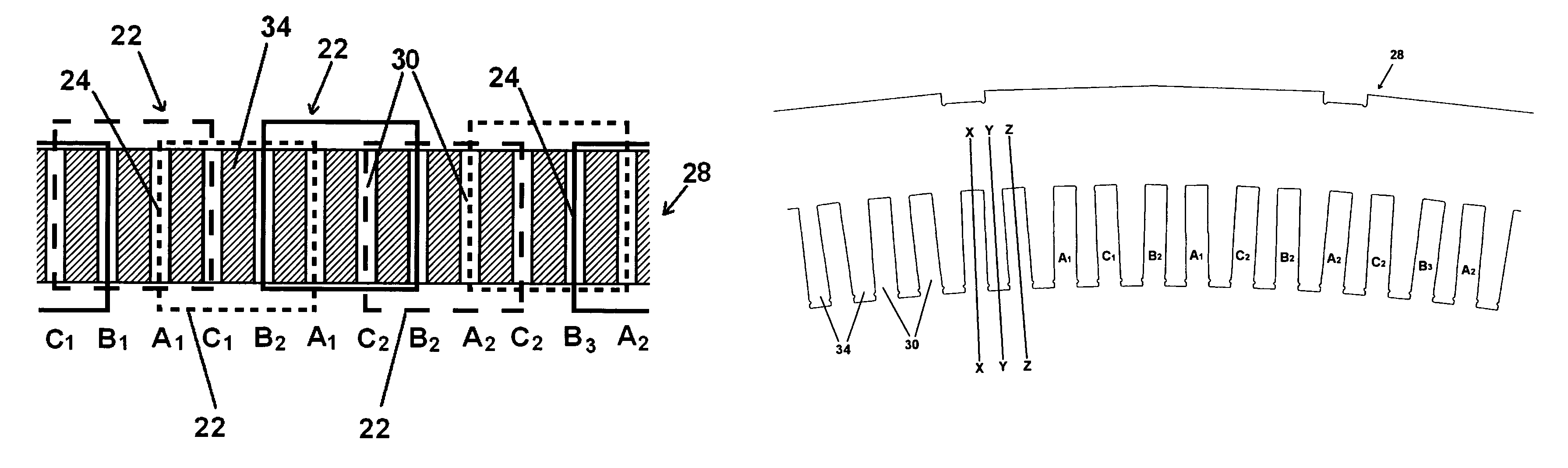
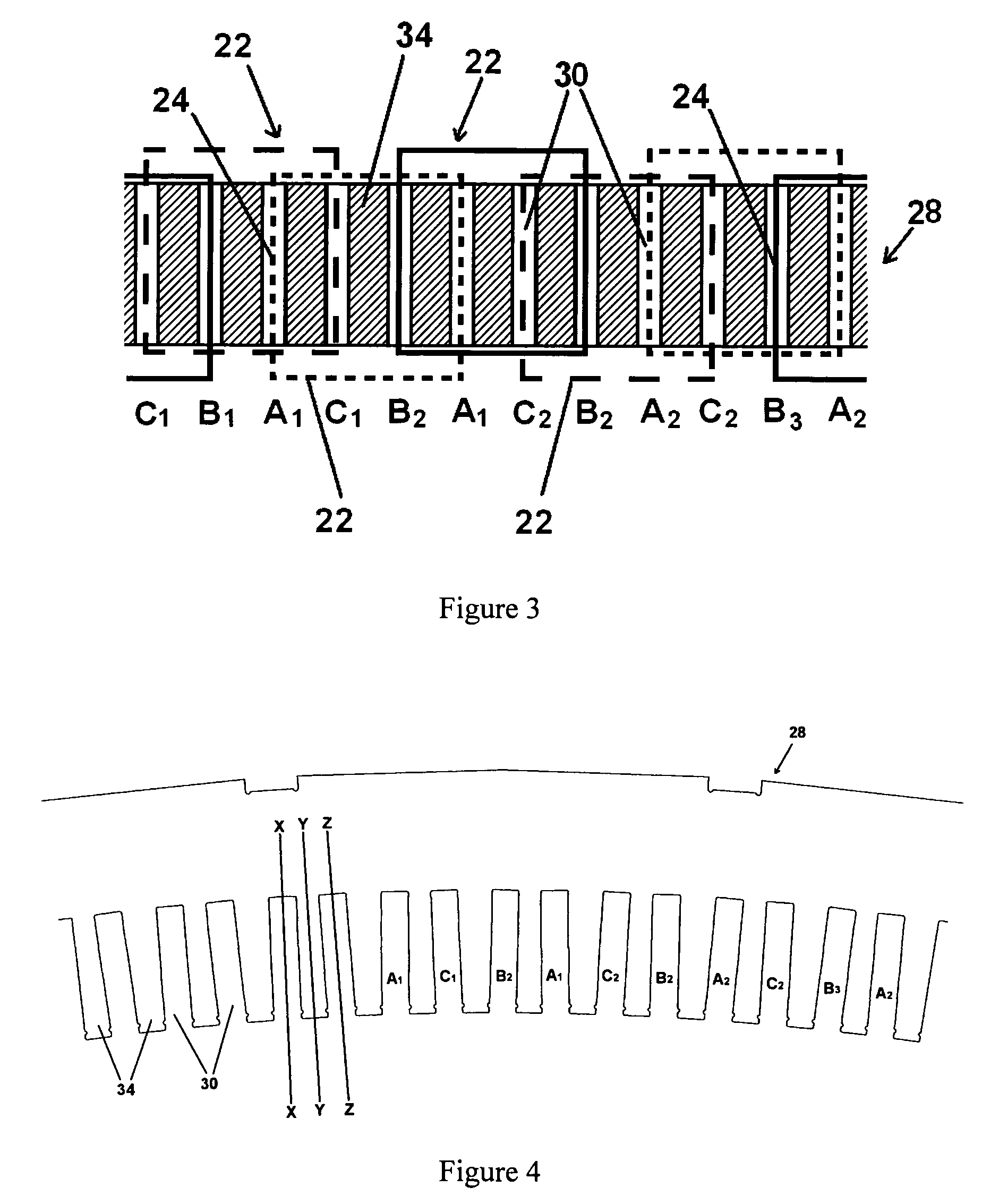
[0041]FIG. 3 shows a stator that has a three-phase two-tier single-layer stator winding with one slot-per-pole-per-phase. The stator 28 is shown in a highly schematic manner in order to show the stator winding and it will be readily appreciated that the illustrated dimensions of the stator 28 do not correspond to the actual dimensions. FIG. 3 is oriented such that the radii of the stator 28 extend into the paper, the longitudinal axis of the stator 28 is parallel to the vertical direction of the paper and the circumference of the stator 28 is parallel to the horizontal direction of the paper. The section of the stator 28 that is shown in FIG. 3 includes twelve winding slots 30 and each slot contains the axially-extending winding run 24 of a pre-formed coil 22. Each coil 22 has a pitch of three winding slots 30 and the two winding runs 24 of each coil 22 are therefore contained in winding slots 30 that are separated by two intermediate winding slots. As the stator 28 contains a three...


PUM


Abstract

An improved stator (28) for rotating electrical machines with single-layer stator windings consisting of a plurality of pre-formed coils (22) of equal angular pitch. The stator (28) has a first cylindrical surface in which a plurality of circumferentially spaced winding slots (30) are formed and in which the axially-extending winding runs (24) of the pre-formed coils (22) are positioned. The two winding runs (24) of each coil (22) will each be positioned in a winding slot (30) and the two winding slots (30) that receive the coil (22) define a winding slot pair. The improvement arises from the fact that the winding slots (30) of each winding slot pair extend into the stator (28) in substantially parallel directions. This means that the axially-extending winding runs (24) of each pre-formed coil (22) may also be substantially parallel and need not be angled towards each other. This enables the stator (28) to be easily wound as each pre-formed coil (22) may be simply and easily slotted into a parallel winding slot pair.

Description

CROSS REFERENCE TO RELATED APPLICATIONS[0001]This application is a U.S. National Stage of PCT / GB2007 / 003569 which claims priority to GB Patent Application No. 0619538.2 filed Oct. 4, 2006.FIELD OF THE INVENTION[0002]The present invention relates to rotating electrical machine, and in particular to electrical machines that have single-layer stator windings that are formed by slotting pre-formed coils into open-type winding slots formed in a stator and provides a novel stator for such electrical machines.BACKGROUND OF THE INVENTION[0003]A common method of forming single-layer stator windings in large rotating electrical machines is to slot a plurality of pre-formed coils into open-type winding slots formed in a surface of the stator. The coils are formed separately from the stator and then individually dropped into position in the winding slots during the winding process. Each pre-formed coil is constructed from one or more insulated conductors as a complete loop and has several turns...

Claims


Application Information

Patent Timeline
Patent Type & Authority Patents(United States)
IPC IPC(8): H02K1/16
CPCH02K1/165H02K15/024H02K15/065
Inventor CLARK, PAUL EATON
Owner GE POWER CONVERSION
Why Eureka
Try Eureka