Jewelry organizer

Active Publication Date: 2020-04-23
MARTINO MARC GREGORY
View PDF0 Cites 1 Cited by
  • Summary
  • Abstract
  • Description
  • Claims
  • Application Information

AI Technical Summary

Benefits of technology

[0024]An exemplary embodiment of a watercraft powered by a rider includes a floatable board having a top side and a bottom side, wherein the top side is sufficient to accept the rider laying face down on the floatable board and wherein the bottom side is submerged below a water line. A leg extension bar is pivotally connected to the floatable board wherein the leg extension bar has a distal leg extension bar end and a proximal leg extension bar end where the proximal leg extension bar end is pivotally connected to the floatable board and where an ankle engagement fixture is attached at the distal leg extension bar end which interfaces with a rider's ankles. A fin extension bar is pivotally connected to the floatable board wherein the fin extension bar has a proximal fin extension bar end and a distal fin extension bar end where the proximal fin extension bar end is pivotally connected to the floatable board on the bottom side and allows the fin extension bar to travel in an arcuate path, and where a fin is attached at the distal fin extension bar end, thereby creating thrust. A means is included for mechanically coupling the leg extension bar to the fin extension bar. The means for mechanically coupling the leg extension bar to the fin extension bar may be accomplished with a reduction ratio wherein an amount of rotation of the leg extension bar results in a lesser rotation of the fin extension bar. The means for mechanically coupling the leg extension bar to the fin extension bar may be such that the leg extension bar and fin exte

Problems solved by technology

Third, a wall mounted doll house is designed to replace large three-dimension

Method used


Image

  • Jewelry organizer
  • Jewelry organizer
  • Jewelry organizer

Examples


Embodiment Construction

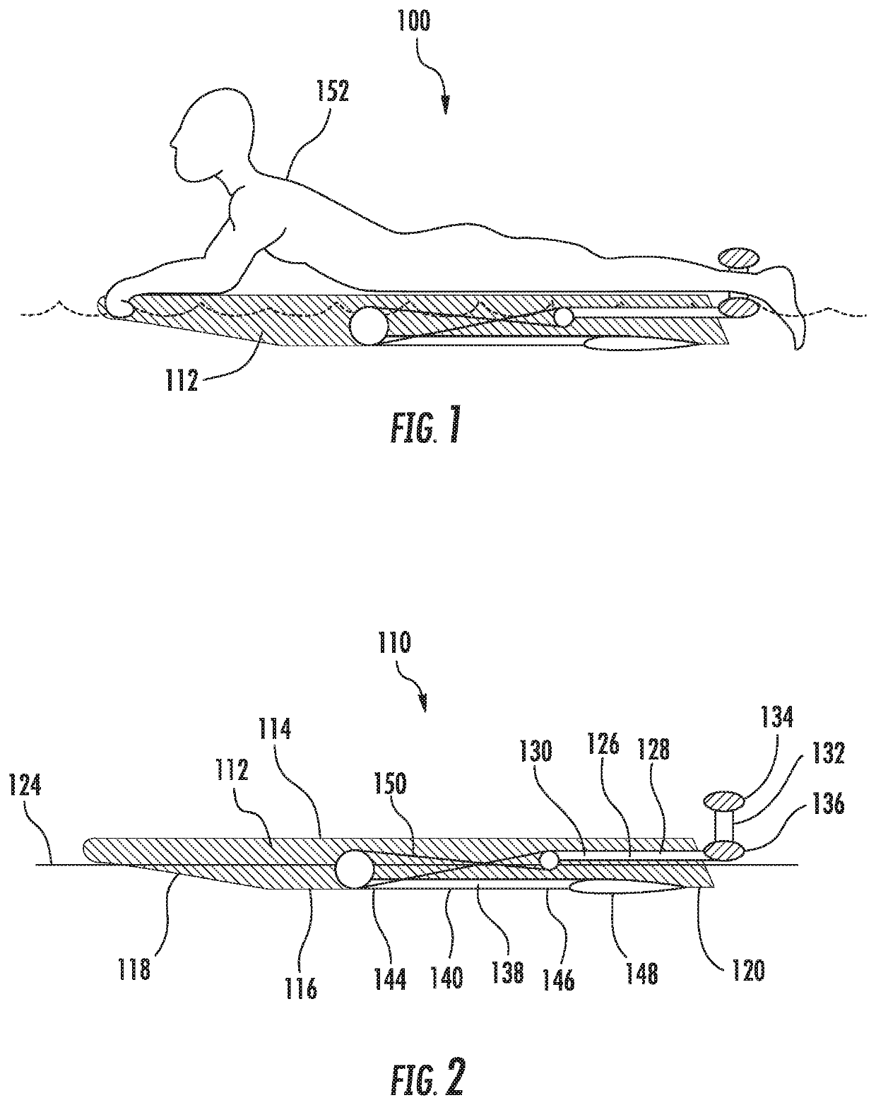
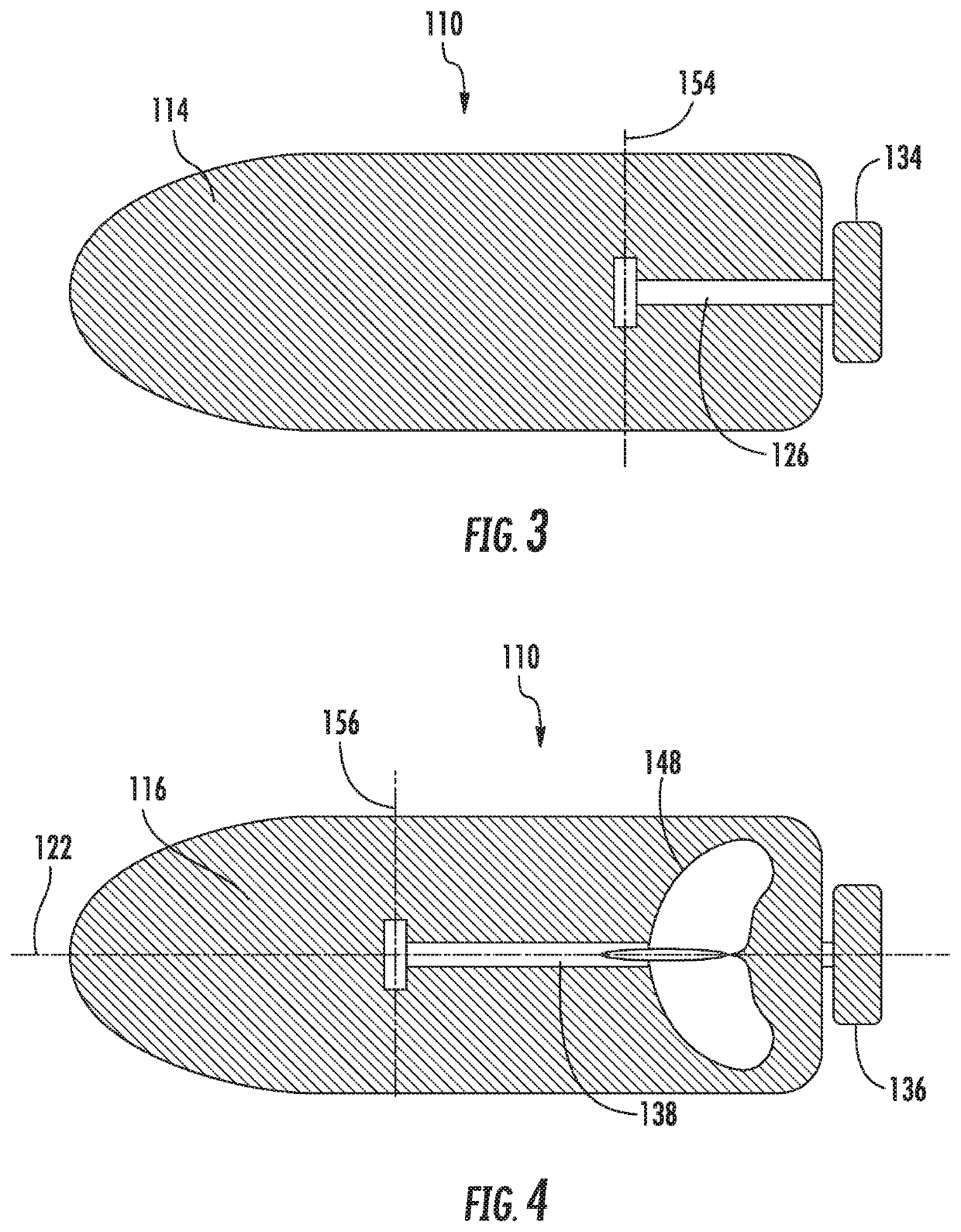
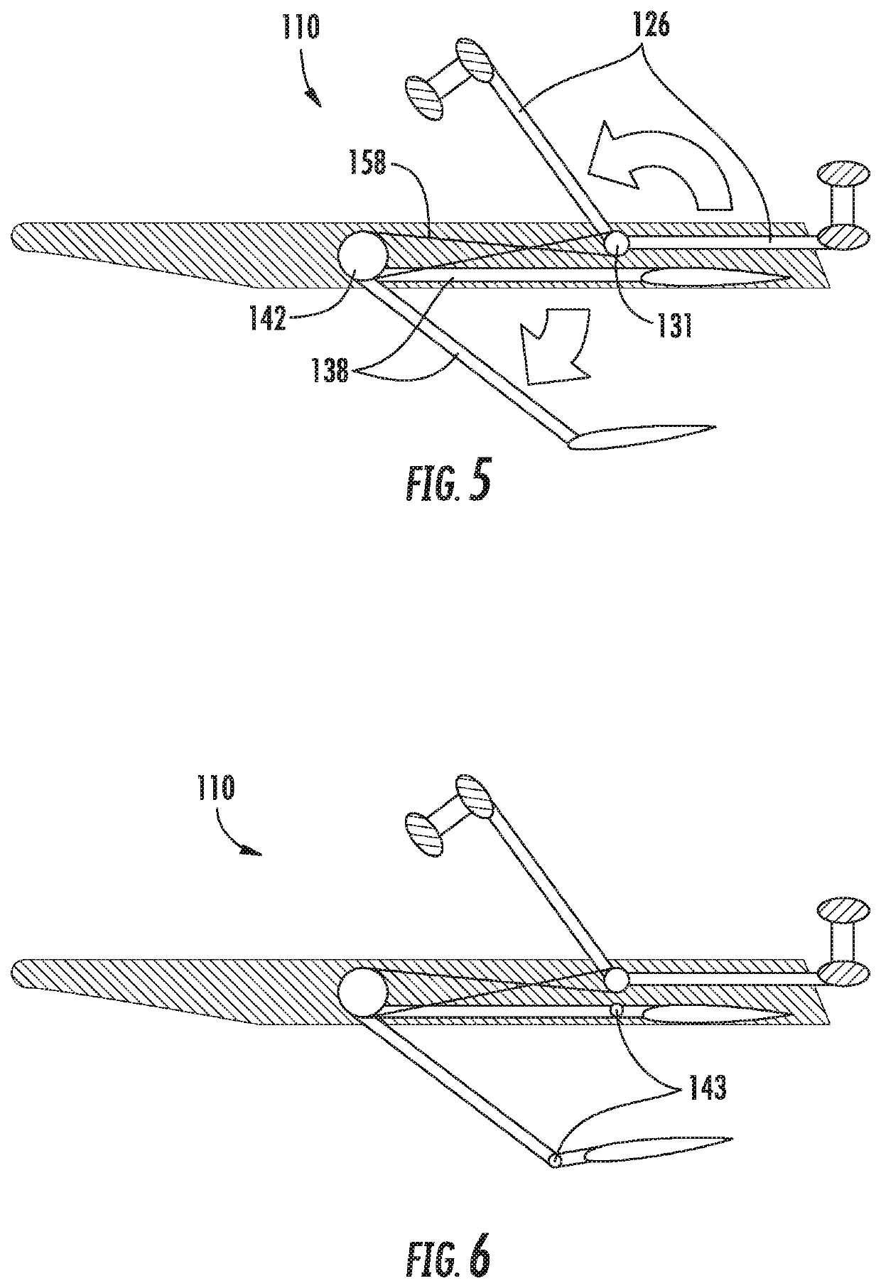
[0063]Invention 1: Dolphin Board

[0064]Many worldwide enjoy water related activities using surfboards, boogie boards, body boards and the like in swimming pools, lakes, rivers, and in the oceans. These buoyant boards are normally powered by the rider in a prone position, as the rider lies on his stomach on top of the board. The rider then creates propulsion by paddling with his hands. The arms are not the largest muscle group normally intended for propulsion, and after a short duration the rider can quickly tire. This is even more noticeable when paddling through the ocean surf, as much energy is needed to push through the surging waves. Furthermore, paddling in this manner also requires advanced balancing skills as the rider cannot simultaneously hold onto the board while paddling. This is especially apparent with smaller sized boards, where not all of the weight of the rider is supported by the board but rather hangs into the water, such as a boogie board. A need exists for channel...


PUM


Abstract

A jewelry display includes a ferromagnetic planar substrate and a bracket configured to be attached to a wall. The bracket has at least one wall engagement surface disposed along an inner surface and at least one ferromagnetic planar substrate engagement surface disposed along an outer surface. An adhesive backed non-slip covering adhesively attaches to the substrate engagement surface. At least one bracket magnet is disposed on the inner surface of the bracket. A plurality of jewelry fixtures are configured to be removably attached to the front surface of the ferromagnetic planar substrate, each jewelry fixture having at least one permanent fixture magnet and a jewelry holding structure, where the at least one permanent fixture magnet of each jewelry fixture is magnetically attracted to the ferromagnetic planar substrate.

Description

CROSS-REFERENCE TO RELATED APPLICATIONS[0001]This continuation-in-part application claims priority to continuation-in-part application Ser. No. 15 / 810,146 filed on Nov. 13, 2017, which itself claims priority to continuation application Ser. No. 14 / 294,591 filed on Jun. 3, 2014, which itself claims priority to non-provisional patent application Ser. No. 13 / 456,213 filed on Apr. 26, 2012 (now U.S. Pat. No. 8,763,551 issued on Jul. 1, 2014), which itself claimed priority to provisional patent application No. 61 / 480,645, filed on Apr. 29, 2011, the contents of which all applications herein are incorporated in full with these references.DESCRIPTIONField of the Invention[0002]The present invention relates in general to a jewelry organizer, and in particular to a wall mounted jewelry organizer that allows the user to easily see and configure one's jewelry.Background of the Invention[0003]This application covers several different inventions. First, a dolphin board is a propulsion enhanced f...

Claims


Application Information

Patent Timeline
IPC IPC(8): A47F5/08F42B10/34F42B6/10B63H16/18B63H1/36A63H18/04A63H3/52
CPCF42B10/34A47F7/02F42B6/10A63H3/52A47F5/0876B63B32/20F01N2260/06A47F5/0807A63H18/04F01N13/082B63H1/36B63H16/18B63B1/30B63B32/22B63B32/60F41B6/00F41B7/003F41B7/08F42B6/006F42B10/06F42B10/26
Inventor MARTINO, MARC GREGORY
Owner MARTINO MARC GREGORY
Why Eureka
Try Eureka