
Structure monitoring system and structure monitoring method

a monitoring system and monitoring method technology, applied in the direction of structural/machine measurement, elasticity measurement, instruments, etc., can solve problems such as vibration abnormality, and achieve the effect of accurately monitoring the degree of soundness

Inactive Publication Date: 2017-04-06
SEIKO EPSON CORP
View PDF5 Cites 4 Cited by
  • Summary
  • Abstract
  • Description
  • Claims
  • Application Information

AI Technical Summary

Benefits of technology

The invention provides a system and method to monitor the soundness (health) of a structure with metal parts more accurately. This helps to ensure the structure is sound and safe for use.

Problems solved by technology

However, there is a problem in that causes of the abnormality of the vibration (for example, whether or not the abnormality is abnormality of the vibration due to the deterioration of the rebars) cannot be specified.

Method used


Image

  • Structure monitoring system and structure monitoring method
  • Structure monitoring system and structure monitoring method
  • Structure monitoring system and structure monitoring method

Examples


first embodiment

[0046]First, a first embodiment of the invention will be described.

[0047]Structure Monitoring System

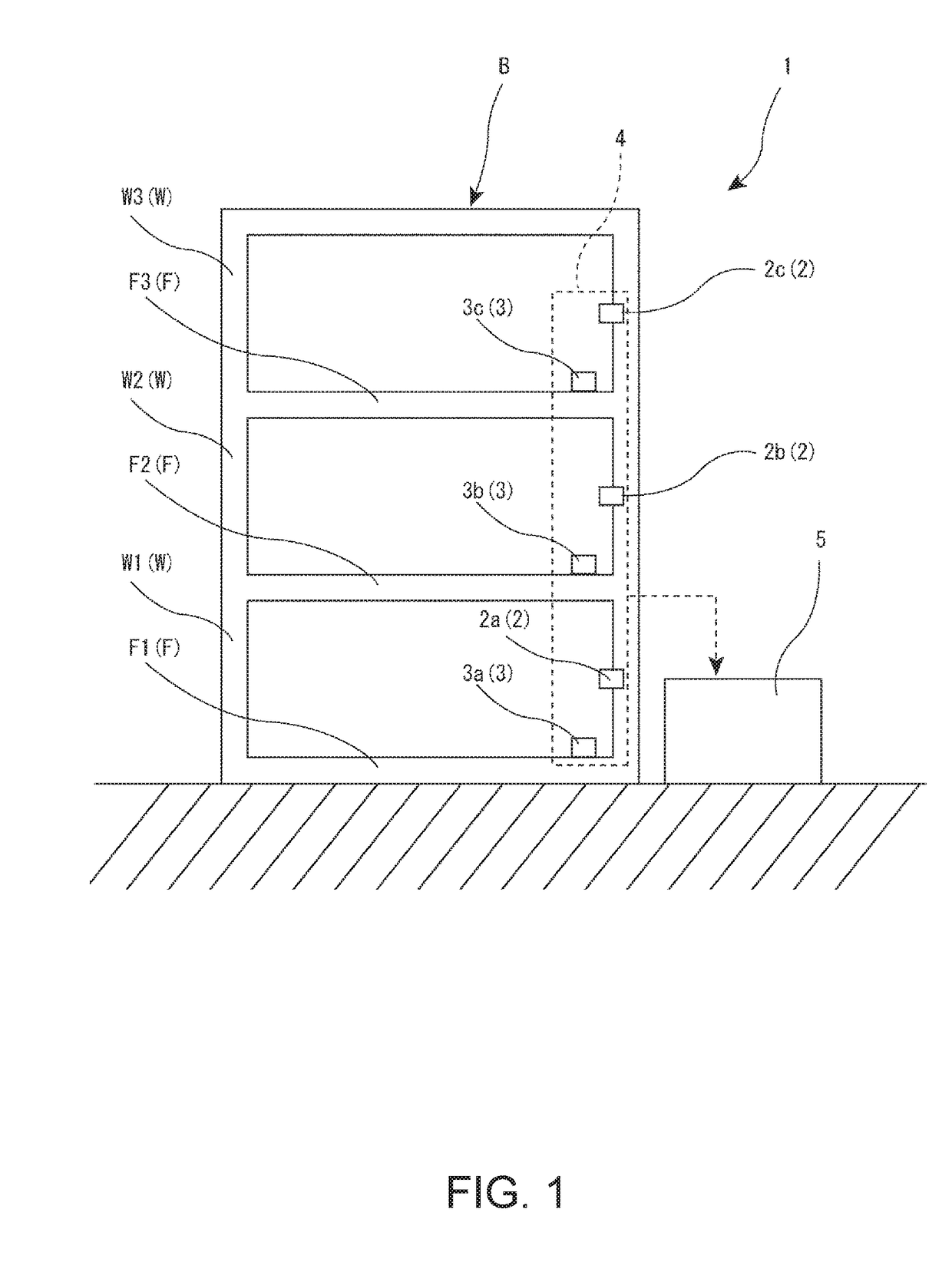
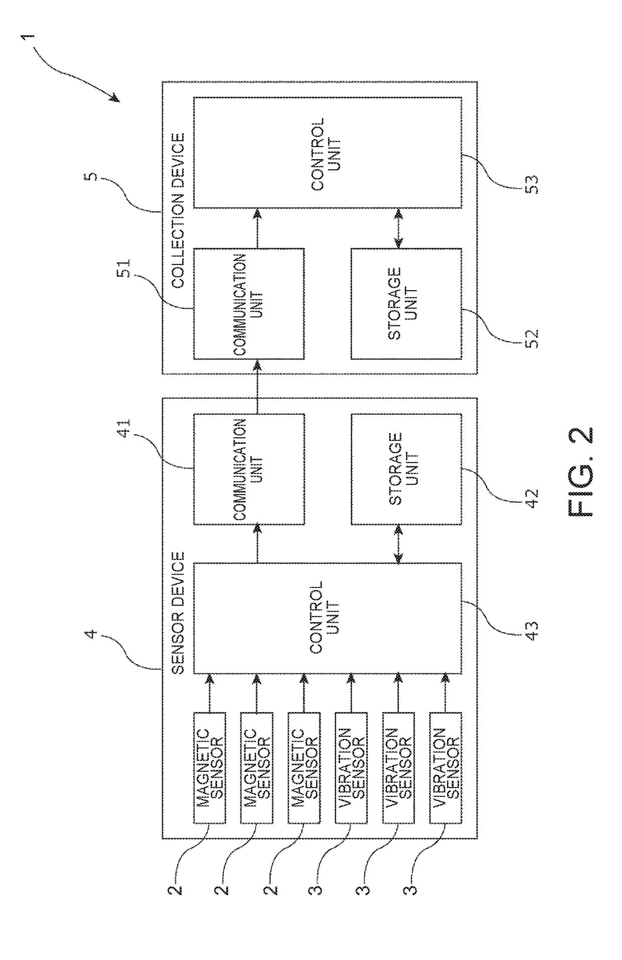
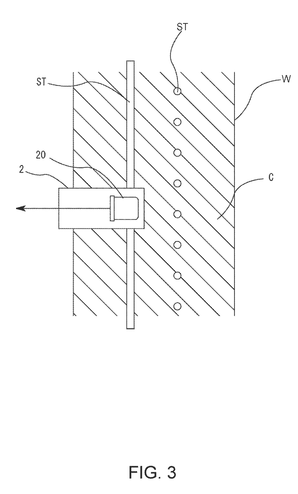
[0048]FIG. 1 is a diagram illustrating an example of a use state of a structure monitoring system according to a first embodiment of the invention. FIG. 2 is a block diagram illustrating a schematic configuration of the structure monitoring system illustrated in FIG. 1. FIG. 3 is a diagram illustrating an installation state of a magnetic sensor included in the structure monitoring system illustrated in FIG. 1. FIG. 4 is a cross-sectional view of a sensor body portion included in the magnetic sensor illustrated in FIG. 3. FIG. 5 is a block diagram illustrating a control system of the magnetic sensor illustrated in FIG. 3. FIG. 6 is a graph illustrating a relationship between a magnetic flux density and an energy transition state of cesium atoms.

[0049]The structure monitoring system 1 (hereinafter simply referred to as a “system 1”) illustrated in FIG. 1 monitors a degree of soundness (...

second embodiment

[0139]Next, a second embodiment of the invention will be described.

[0140]FIG. 10 is a diagram illustrating a schematic configuration of a magnetic sensor used in the structure monitoring system according to a second embodiment of the invention.

[0141]Hereinafter, the second embodiment will be described by focusing on a difference between the above-described embodiment and the second embodiment, and description of the same matters will be omitted.

[0142]The second embodiment is the same as the first embodiment except that the configuration of the magnetic sensor is different. The same configuration as in the above-described embodiment is denoted with the same reference numeral.

[0143]The magnetic sensor 2A used in this embodiment includes a light source unit 222A, a polarization plate 261, a half mirror 262, an atom cell 221, a mirror 263, a polarization separator 264, a light detection unit 225a, and a light detection unit 225b. In FIG. 10, for convenience of description, an x-axis, a ...


PUM


Abstract

A structure monitoring system includes a magnetic sensor that detects an intensity of a magnetic field from a structure including a metal portion using characteristics of an energy transition of alkali metal atoms, and a control unit that determines a degree of soundness (a degree of fatigue of the metal portion) of the structure using a result of the detection of the magnetic sensor.

Description

CROSS REFERENCE[0001]This application claims the benefit of Japanese Application No. 2015-197948, filed on Oct. 5, 2015. The disclosure of the prior application is hereby incorporated by reference herein in its entirety.BACKGROUND[0002]1. Technical Field[0003]The present invention relates to a structure monitoring system and a structure monitoring method.[0004]2. Related Art[0005]A structure monitoring system that monitors a degree of soundness of a structure including a metal portion such as rebars or steel frames is known (see, for example, Non-Patent Document 1 (Kouichi Sato, et al., “Basic Study for development of structure monitoring system”, Taisei Technology Center Report, Taisei Corporation, 2010, No. 43)).[0006]For example, in a system described in Non-Patent Document 1, an acceleration sensor is installed in a structure, and a state (soundness) of the structure is confirmed using a detection result of the acceleration sensor.[0007]In the system described in Non-Patent Docu...

Claims


Application Information

Patent Timeline
Patent Type & Authority Applications(United States)
IPC IPC(8): G01M5/00G01R33/032
CPCG01M5/0091G01M5/0066G01R33/032G01M5/0033
Inventor MAKI, YOSHIYUKI
Owner SEIKO EPSON CORP
Learn More