Method for manufacturing glass light guide plate having high transmission efficiency

a technology of transmission efficiency and light guide plate, which is applied in the direction of manufacturing tools, planar/plate-like light guides, instruments, etc., can solve the problems of reducing light guide efficiency, reducing the possibility of reflection of light, and reducing the efficiency of light guide plate. , to achieve the effect of enhancing light guide efficiency, reducing the possibility of reflection of light, and increasing the incident amount of ligh

Inactive Publication Date: 2017-04-13
CHENFENG OPTRONICS CORP
View PDF0 Cites 2 Cited by
  • Summary
  • Abstract
  • Description
  • Claims
  • Application Information

AI Technical Summary

Benefits of technology

[0005]It is a primary object of the present invention to solve issues of decreased light entering a glass light guide plate and reduced light guide efficiency caused by a rounded corner liable to reflecting light.
[0010]1. The light guide surface is formed by heating and extruding the light incident surface of the glass plate. As the area of the light guide surface is greater than the area of the light incident surface, incident light is less likely to irradiate upon corners of the light guide surface, thereby reducing the possibility of reflection of the light and enhancing light guide efficiency.
[0011]2. With the area of the light guide plate being greater than the area of the light incident surface, the incident amount of light is increased to enhance light guide efficiency.
[0012]3. Through the method for manufacturing the light guide portion by heating and extrusion using the thermoplastic machine, the light guide portion is formed as an integral on the glass plate, thereby preventing an issue of brightness loss due light reflection caused by additionally manufactured light guide elements.

Problems solved by technology

However, during the course of processing glass into a light guide plate having an appropriate size, glass is cut, and extremely sharp corners that easily cut operating staff during processes of moving or manufacturing can be formed.
However, referring to FIG. 1, a rounded corner 1 increases the possibility of reflecting a light 2, such that the light entering a glass light guide plate is decreased and light guide efficiency is reduced.

Method used


Image

  • Method for manufacturing glass light guide plate having high transmission efficiency
  • Method for manufacturing glass light guide plate having high transmission efficiency
  • Method for manufacturing glass light guide plate having high transmission efficiency

Examples


Embodiment Construction

[0021]Details and technical contents of the present invention are given with the accompanying drawings below.

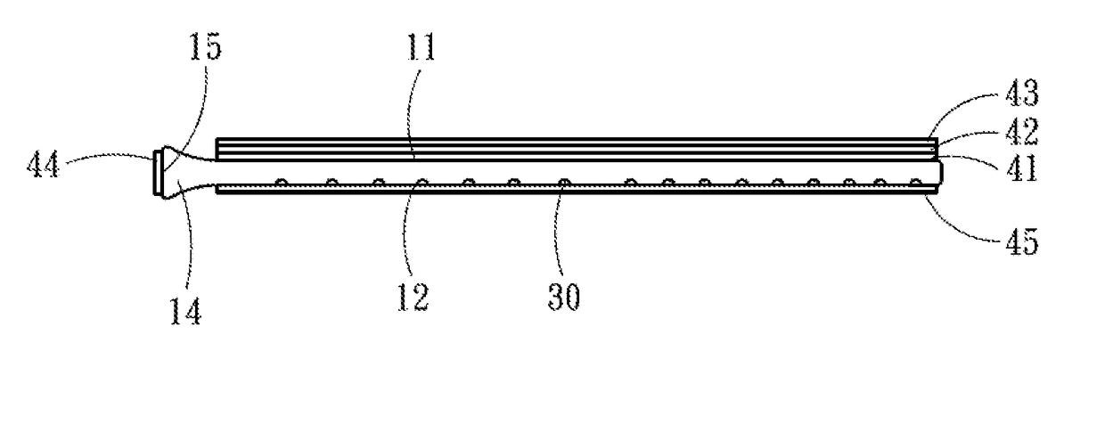
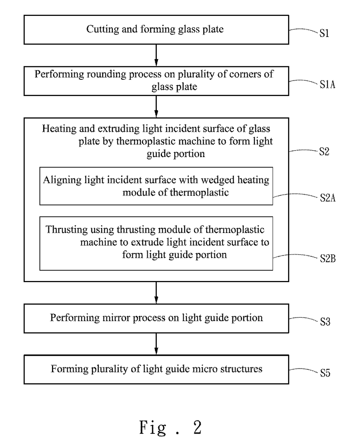
[0022]FIG. 2 to FIG. 6 show a schematic diagram of a manufacturing process, consecutive schematic diagrams of manufacturing a structure, and a top structural schematic diagram according to a first embodiment of the present invention, and a side structural schematic diagram and a partial schematic diagram of an incident light according to a second embodiment of the present invention. Referring to FIG. 2 to FIG. 6, a method for manufacturing a glass light guide plate having high transmission efficiency of the present invention includes following steps.

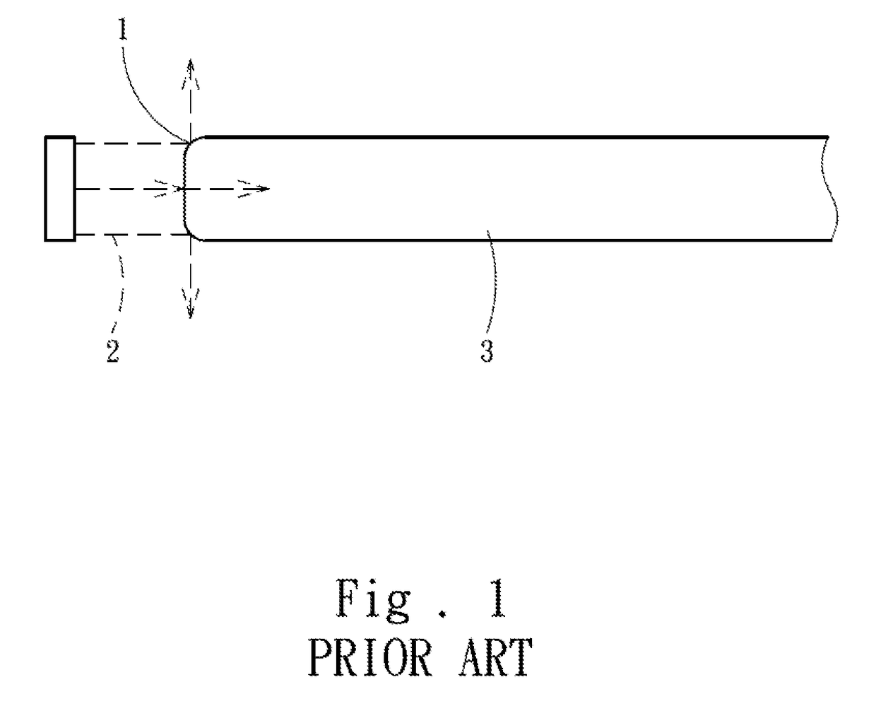
[0023]In step S1, a glass plate 10 is cut and formed using a cutter machine (not shown). The glass plate 10 includes a first flat surface 11 and a second flat surface 12 that are opposite and parallel to each other, and a light incident surface 13 perpendicular and connected to the first flat surface 11 and the second flat surface...


PUM

PropertyMeasurementUnit
Raaaaaaaaaaa
transmission efficiencyaaaaaaaaaa
areaaaaaaaaaaa

Abstract

A method for manufacturing a glass light guide plate having high transmission efficiency is provided. A glass plate is cut and formed using a cutter machine. The glass plate includes a first flat surface and a second flat surface that are opposite and parallel to each other, and a light incident surface perpendicular and connected to the first flat surface and the second flat surface. The light incident surface is heated and extruded using a thermoplastic machine to deform the light incident surface to form a light guide portion. The light guide portion includes a light guide surface perpendicular to the first flat surface and the second flat surface, and has an area greater than an area of the light incident surface. When a light enters via the light guide surface, the amount of light irradiating corners of the light guide surface is reduced.

Description

FIELD OF THE INVENTION[0001]The present invention relates to a method for manufacturing a light guide plate, and particularly to a method for manufacturing a light guide plate having high transmission efficiency.BACKGROUND OF THE INVENTION[0002]One main function of a light guide plate is guiding propagation directions of light beams using principles of total reflection and scattering. After entering via a light incident surface of a light guide plate, a beam undergoes total reflection and scattering in the light guide plate. The light beam then exits in a uniform manner from a light emission surface of the light guide plate, hence allowing a point light source or a line light source to become a plane light source that can be extensively applied in fields of display and illumination devices.[0003]The U.S. Pat. No. 7,478,942, “Light Guide Plate with Light Reflection Pattern” disclosed a light guide plate. The light guide plate of the disclosure includes a light incident surface that r...

Claims


Application Information

Patent Timeline
Patent Type & Authority Applications(United States)
IPC IPC(8): F21V8/00C03B23/02
CPCG02B6/0065G02B6/002C03B33/02G02B6/0061C03B23/02G02B6/0043C03B23/002G02B6/0036
Inventor WONG, CHING-FANGLIU, YU-WEI
Owner CHENFENG OPTRONICS CORP
Why Eureka
Try Eureka