
Staples push unit for tackers

a push unit and tacker technology, applied in the field of tacker, can solve problems such as affecting the precision of the ejection of staples

Active Publication Date: 2017-04-20
HUANG TSUNG WEN
View PDF2 Cites 1 Cited by
  • Summary
  • Abstract
  • Description
  • Claims
  • Application Information

AI Technical Summary

Benefits of technology

The invention is a staple push unit for a tacker. Its unique feature is that the driving gear's teeth directly engage the rack of the slide, ensuring stable and precise transmission of power. This results in a more efficient and reliable staple push unit.

Problems solved by technology

This may affects the precision of the ejection of the staples.

Method used


Image

  • Staples push unit for tackers
  • Staples push unit for tackers
  • Staples push unit for tackers

Examples


Embodiment Construction

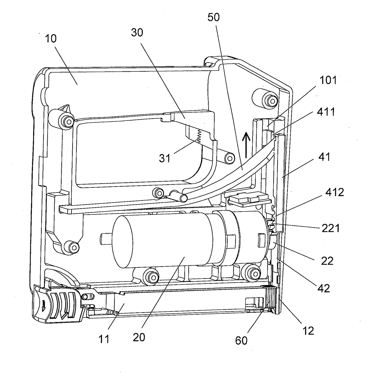
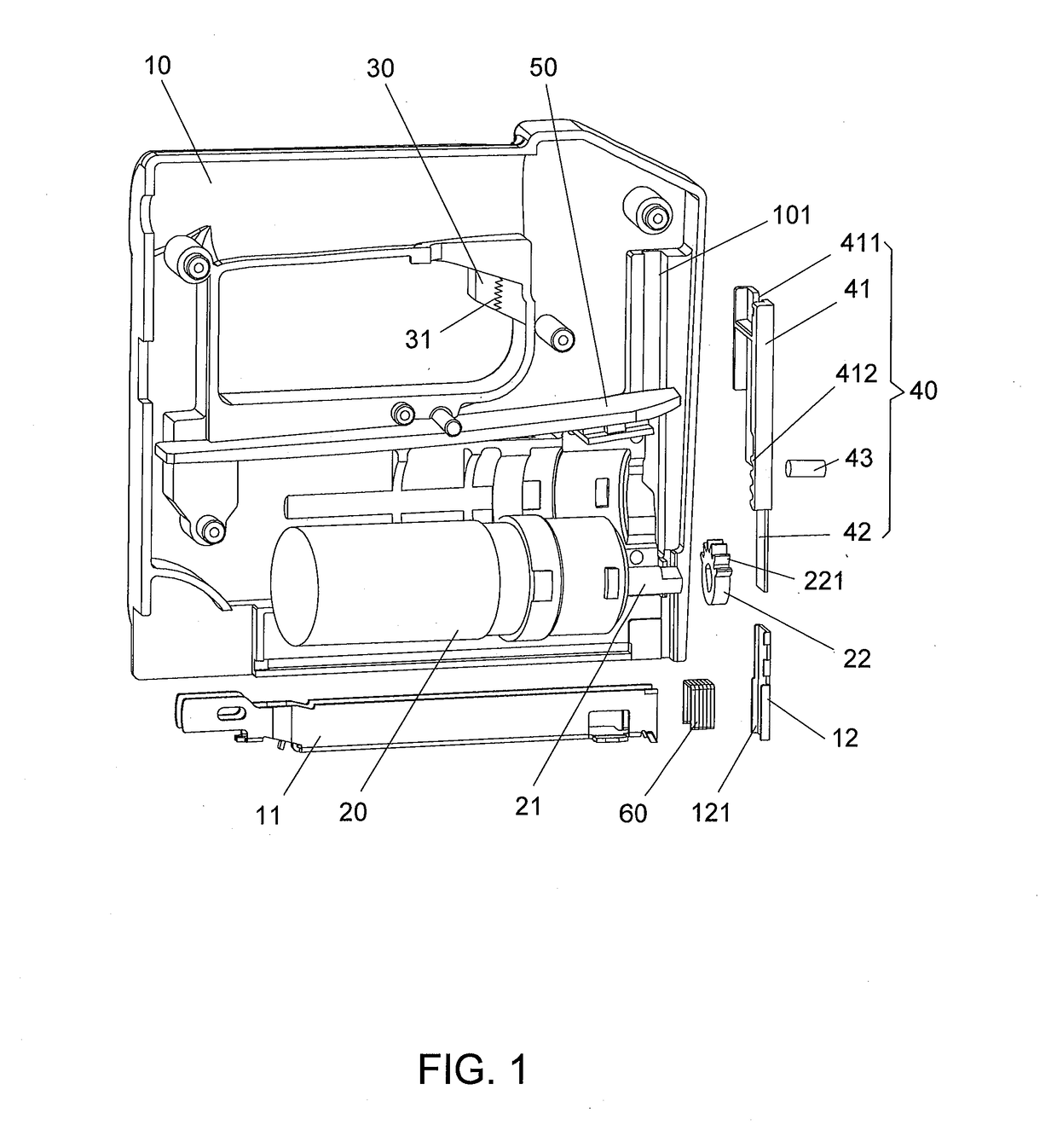
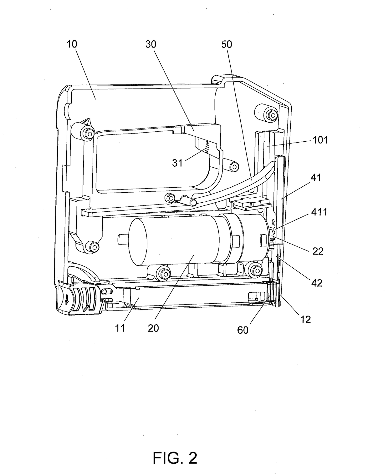
[0026]Referring to FIGS. 1 to 7, the staples push unit of a tacker 10 of the present invention comprises a magazine 11 connected to the front end of the tacker 10, the magazine 11 has an opening at the top thereof. Staples are receive staples 60 in the magazine 11 and pushed by a pushing mechanism in the magazine 11 toward the opening. A slot 101 is defined in the tacker 10 and perpendicular to the magazine 11. A guide plate 12 is located in the tacker 10 and located at the staple outlet of the tacker 10 and above the opening of the magazine 11.

[0027]A motor 20 is located in the tacker 10 and has an output shaft 21. A driving gear 22 is connected to the output shaft 21 and has teeth 221 defined in a portion of the outer periphery thereof. A trigger 30 is electrically connected to the motor 20 and a spring 31 is located in the trigger 30.

[0028]A push unit 40 is located in the slot 101 and has a slide 41 and a push plate 42 which is connected to the first end of the slide 41 by a pin ...


PUM


Abstract

A staples push unit of a tacker includes a guide plate located at a staple outlet of the tacker. A motor is located in the tacker and has an output shaft to which a driving gear is connected. A slide and a push plate connected to the slide are movably located in a slot in the tacker. A rack is formed at one side of the slide and engaged with the teeth of the driving gear. A spring board has one end engaged with one end of the slide. When activating the motor, the driving gear drives the rack to move the slide, and the spring board is bent. When the teeth of the driving gear are disengaged from the rack, the spring board bounces back and drives the slide and the push plate to eject a staple. The push plate is guided by the guide plate.

Description

BACKGROUND OF THE INVENTION[0001]1. Fields of the Invention[0002]The present invention relates to a tacker, and more particularly, to a staple push unit of a power tacker.[0003]2. Descriptions of Related Art[0004]The conventional tacker known to the applicant is disclosed in FIG. 8, and comprises a motor 70 with an output shaft 72, and a cam 73 is connected to the output shaft 72. A staple push unit is located in the tacker and has a push plate 74, a switch plate 75 and a spring 77, wherein the spring 77 is located in casing 76, and the switch plate 75 is located beside the spring 77. The switch plate75 is driven by the cam 73 so as to simultaneously activate the switch plate 75 and the spring 77. The push plate 74 is located above the switch plate 75. The user pulls the trigger 71 to activate the motor 70 and the output shaft 72 which rotates the cam 73. The cam 73 pushes the switch plate 75 and compress the spring 77 to store energy. As shown in FIG. 9, when the cam 73 rotates ove...

Claims


Application Information

Patent Timeline
IPC IPC(8): A61B17/10A61B17/068
CPCA61B17/068A61B17/105A61B17/064A61B17/0682
Inventor HUANG, TSUNG-WEN
Owner HUANG TSUNG WEN
Learn More