Printing apparatus and method for adjusting a gap

a printing apparatus and gap technology, applied in printing, printing mechanisms, power drive mechanisms, etc., can solve the problems of increasing the size of the carriage, requiring a space in which to be installed, and the adjustment mechanism is relatively large, and requires a large amount of time and manpower

Inactive Publication Date: 2013-10-31
SEIKO EPSON CORP
View PDF1 Cites 3 Cited by
  • Summary
  • Abstract
  • Description
  • Claims
  • Application Information

AI Technical Summary

Benefits of technology

[0022]Furthermore, the head driving mechanism may be constructed so as to include a fixing unit that fixes the movable support member that supports the head plate to the holding unit when the distal end of the adjusting member contacts the surface of the roller. Since such fixing unit always holds the head...

Problems solved by technology

However, this adjusting mechanism is relatively large and requires a space in which to be installed.
Consequently, the adjusting mechanism results in an increase in size of the carriage.
Since the adjusting mechanism adopts a so-called trial and error method in which the mechanism performs operations to adjust and confirms the tilted stat...

Method used


Image

  • Printing apparatus and method for adjusting a gap
  • Printing apparatus and method for adjusting a gap
  • Printing apparatus and method for adjusting a gap

Examples


Embodiment Construction

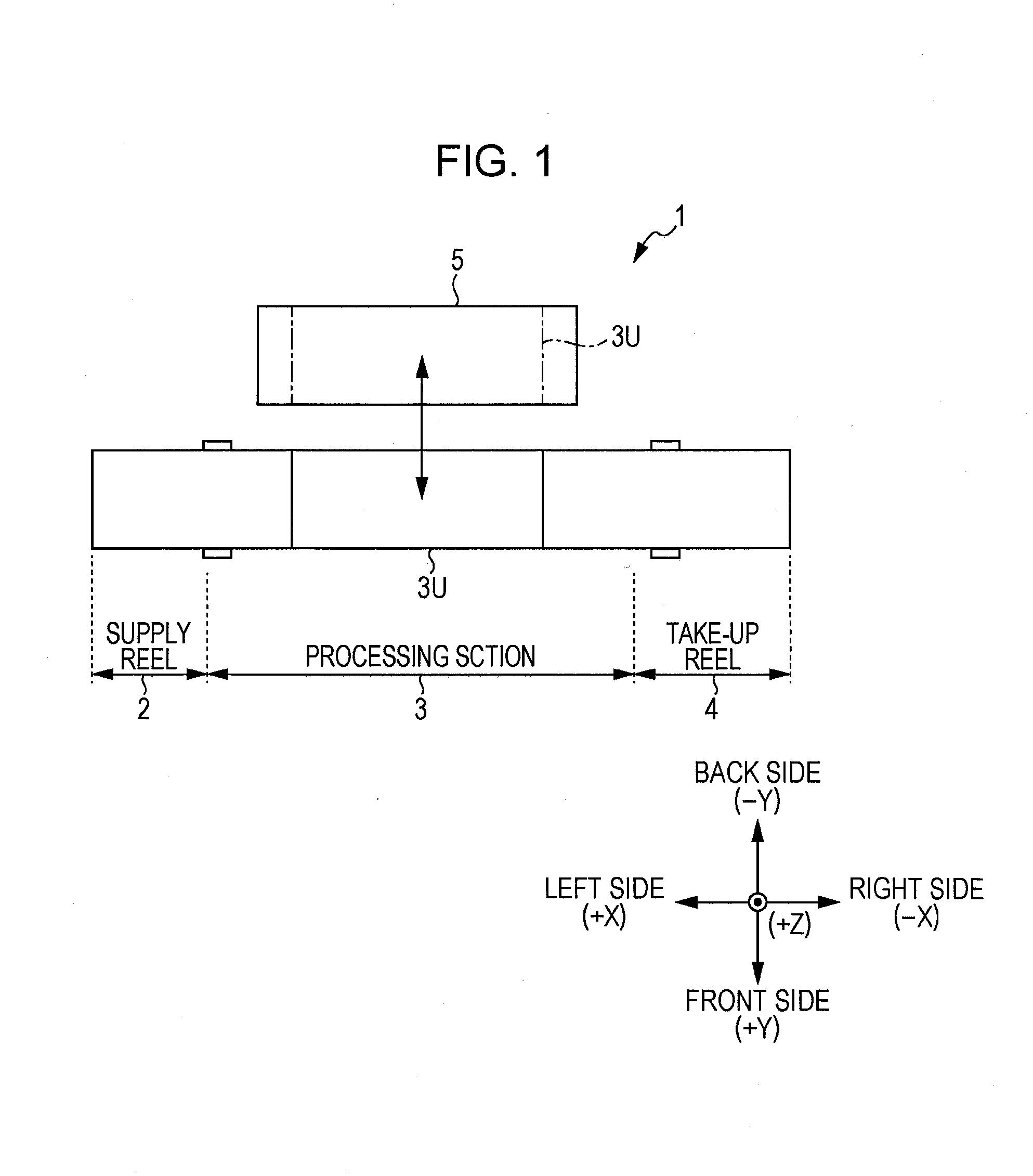
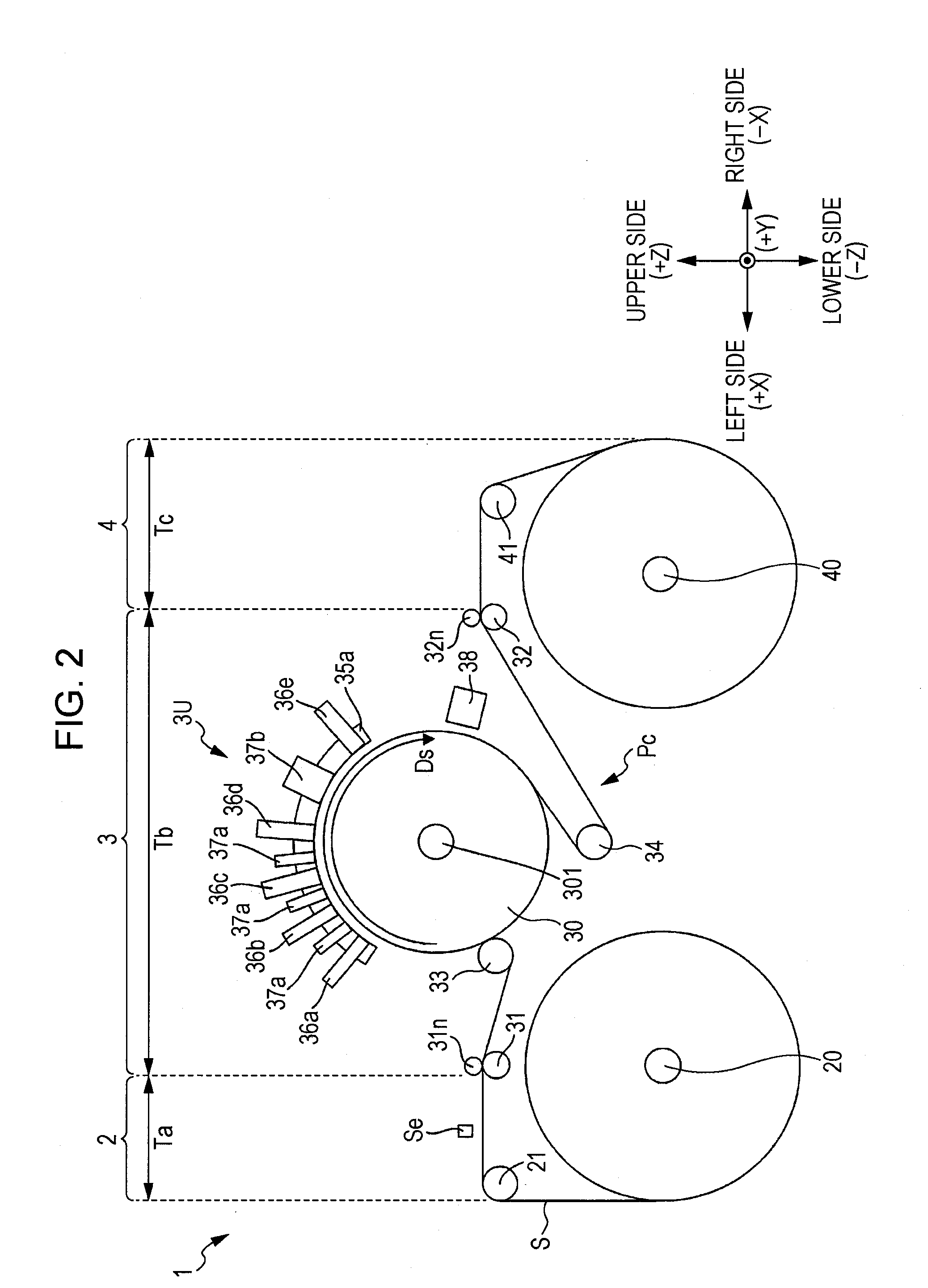
[0032]FIG. 1 is a layout of a first embodiment of a printing apparatus according to the invention. FIG. 2 is a front view schematically illustrating an example of the printing apparatus shown in FIG. 1. In this printing apparatus 1, a supply reel 2, a processing section 3, and a take-up reel 4 are arranged in a left-right direction at a front side of the printing apparatus. A maintenance section 5 is located at a rear side of the processing section 3. A processing unit 3U of the processing section 3 is mounted on the maintenance section 5 so as to be movable. In FIG. 1 and FIG. 2 and the drawings mentioned after, a three-dimensional coordinate system that corresponds to a left-right direction X, a front-back direction Y, and a vertical direction Z in the recording apparatus 1.

[0033]As shown in FIG. 2, the supply reel 2 and the take-up reel 4 in the printing apparatus 1 have a supply reel shaft 20 and a take-up reel shaft 40, respectively. Opposite ends of a sheet (web) S are wrapped...


PUM


Abstract

A printing apparatus includes: a support member that supports a recording medium; a head plate that extends in a direction that intersects a transporting direction of the recording medium; a head body mounted on the head plate and having a nozzle that ejects a liquid onto the recording medium supported on a surface of the support member; and adjusting members that respectively project from opposite ends of the head plate in a direction of the head plate that intersects the transporting direction toward the support member, and that position the head plate with respect to the surface of the support member when each distal end of the adjusting members contacts the surface of the support member.

Description

CROSS-REFERENCE TO RELATED APPLICATIONS[0001]The entire disclosure of Japanese Patent Application No. 2012-100984, filed Apr. 26, 2012 is expressly incorporated by reference herein.BACKGROUND[0002]1. Technical Field[0003]The present invention relates to a printing apparatus which performs a printing operation by ejecting a liquid such as an ink or a recording liquid from a printing head onto a recording medium supported by a supporting member and a method for adjusting a gap.[0004]2. Related Art[0005]JP-A-2011-67964 (FIG. 1) discloses a printing apparatus in which a plurality of printing heads eject liquids such as different inks or recording liquids onto a recording medium such as a film so as to record a color image. In the printing apparatus, the recording medium is wrapped around a cylindrical platen drum in a state of tension being applied to the recording medium and is supported on a curved cylindrical surface. The plural printing heads are disposed around the platen drum so a...

Claims


Application Information

Patent Timeline
IPC IPC(8): B41J2/145
CPCB41J2/145B41J25/308B41J2025/008
Inventor WANIBE, AKIHISA
Owner SEIKO EPSON CORP
Why Eureka
Try Eureka