
Flexible intraocular implant injector

a flexible, intraocular technology, applied in the field of injectors, to achieve the effect of facilitating surgery

Inactive Publication Date: 2011-01-27
CORNEAL IND
View PDF5 Cites 3 Cited by
  • Summary
  • Abstract
  • Description
  • Claims
  • Application Information

AI Technical Summary

Benefits of technology

"The present invention provides a flexible implant injector that can fold the implant and reduce its size, while also being non-reusable after use. The injector includes a channel with a main portion, an open end portion, and a transition portion, and a piston movable in the channel to push the folded implant. A circularly symmetrical thrust part is placed in the channel between the folded implant and the end of the piston without being mechanically connected to the piston. The thrust part is elastically deformable and can penetrate in part into the end portion of the channel to expel the implant. The injector is designed to ensure that the implant is properly ejected into the patient's eye. The thrust part is not mechanically connected to the piston, making it non-reusable. The injector is designed to ensure uniform and regular radial deformation of the thrust part, and the end of the thrust part has a slightly compressed design to prevent jamming with the inside wall of the channel."

Problems solved by technology

That type of injector raises certain problems concerning the action of the piston on the folded implant at the end of its stroke.

Method used


Image

  • Flexible intraocular implant injector
  • Flexible intraocular implant injector
  • Flexible intraocular implant injector

Examples


Embodiment Construction

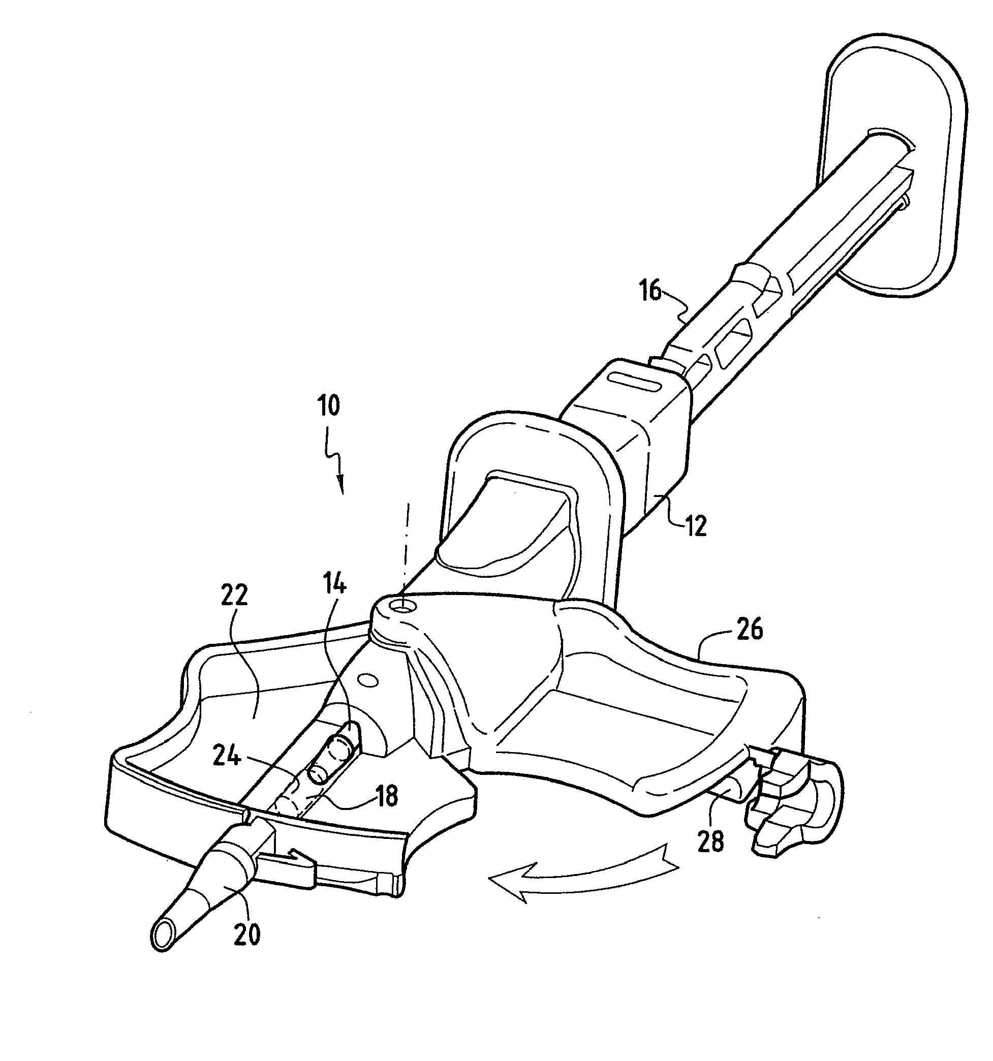
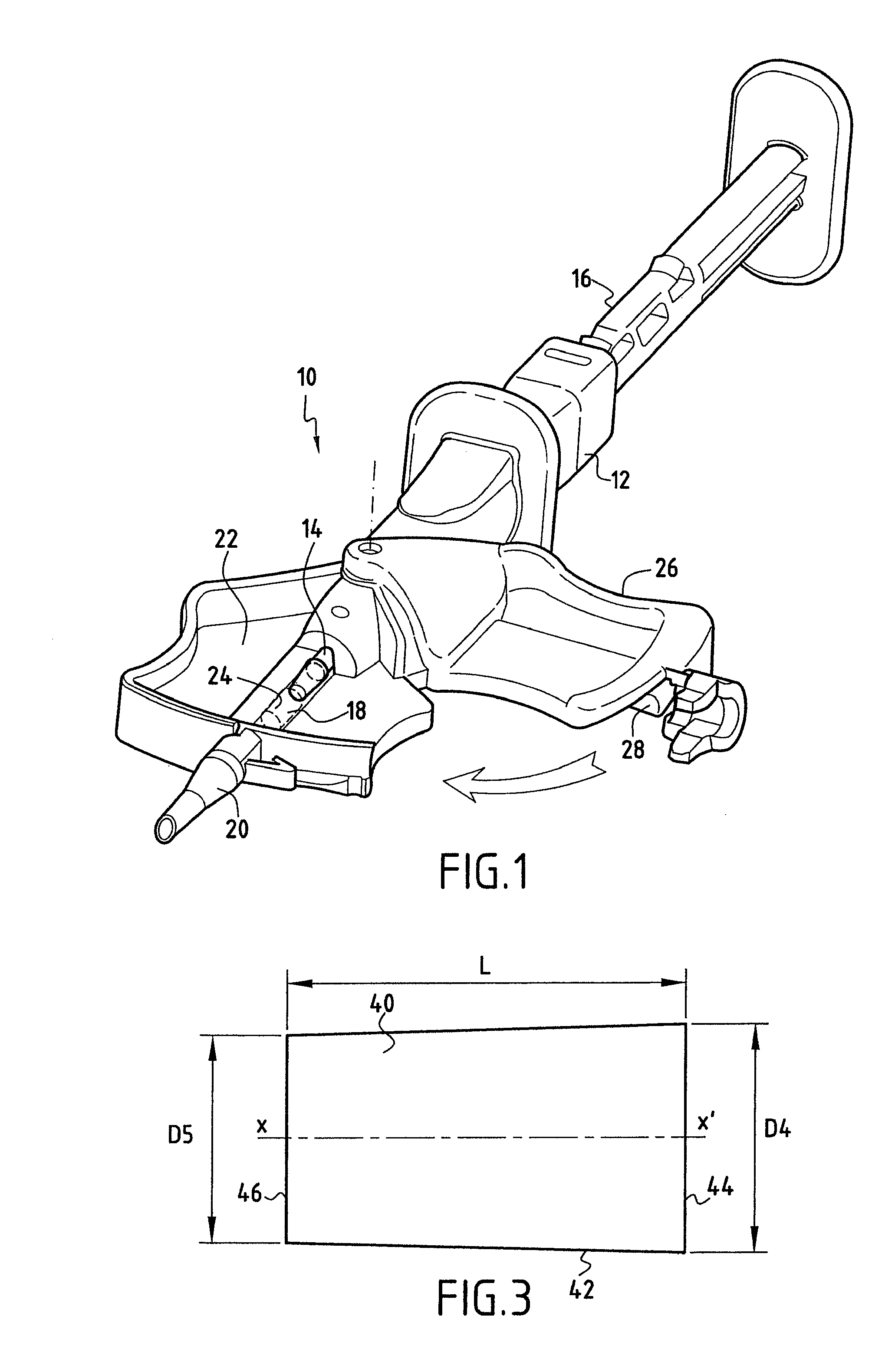
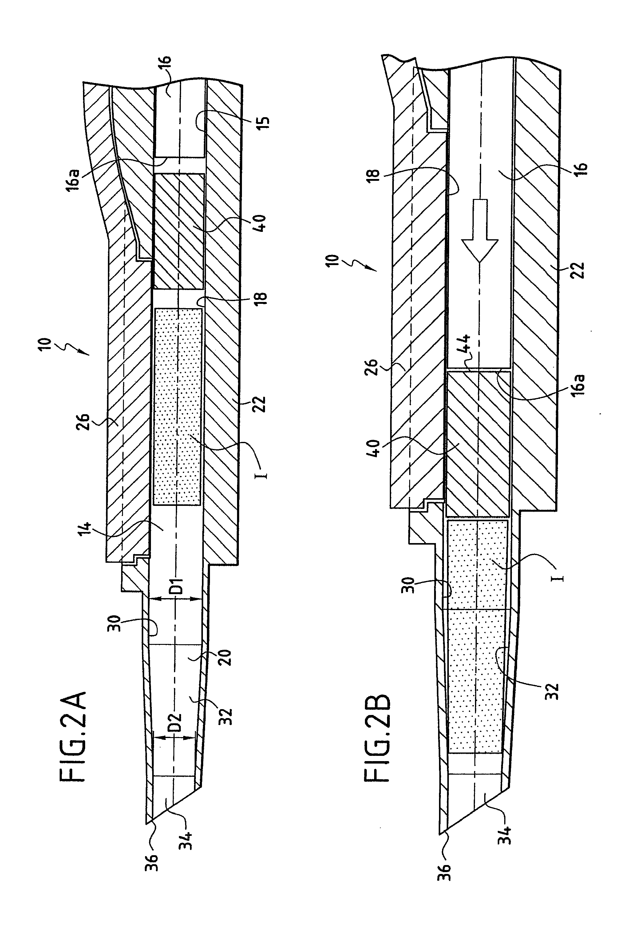
[0022]With reference to FIG. 1, there follows an overall description of a flexible implant injector of the type in question. The injector 10 comprises a body 12 defining a channel 14. The channel 14 has a posterior portion 15 for guiding a piston 16, an intermediate portion 18 constituting a chamber for folding the flexible implant, and an anterior portion 20 constituting a cannula. The folding chamber 18 has a stationary portion 22 defining a first jaw half 24, and a moving portion 26 defining a second jaw portion 28 for folding purposes.

[0023]When a non-folded implant is put into place in the folding chamber 18, and the moving portion 26 is moved towards the stationary portion 22, the flexible implant folds progressively such that at the end of this operation the implant is folded within the folding chamber 18.

[0024]Once the flexible implant has been folded inside the chamber 18, the piston 16 is used to push the folded implant into the cannula 20 that has been inserted into an in...


PUM


Abstract

The injector for injecting a flexible intraocular implant comprises: a channel having a main portion of diameter D1, an open end portion of diameter D2 (with D2<D1), and a transition portion; a rigid piston movable along the channel to push the folded implant in the channel, and a substantially circularly symmetrical thrust part made of a material that is hydrophobic and elastically deformable, said thrust part having an outside diameter D3 not less than D1, said part being placed in said channel between the folded implant and the end of said piston without being mechanically connected to said piston. When the implant is pushed in the channel by the piston, said thrust part can deform elastically to penetrate in part into the end portion of the channel, thereby expelling the implant from the channel, and remaining jammed in said end portion of the channel when the piston is withdrawn.

Description

[0001]This is a continuation of application Ser. No. 11 / 795,336 filed 15 Nov. 2007, which is a 371 national phase application of PCT / FR2006 / / 050030 filed 20 Jan. 2006, claiming priority to French Patent Application No. 0500633 filed 21 Jan. 2005, the contents of which are incorporated herein by reference.BACKGROUND OF THE INVENTION[0002]The present invention provides an injector for injecting a flexible intraocular implant.[0003]Such flexible implant injectors are described in particular in patent applications PCT / FR01 / 01510 and PCT / FR01 / 02994 in the name of the supplier Corneal Industrie.[0004]Flexible intraocular implants are implants having at least the optical portion made of a deformable material such as a hydrophilic or hydrophobic acrylic. The optical portion and also the haptic portion of such implants can be folded or rolled up in such a manner that while in this state the implant can be inserted into the eye through an incision of small size, typically of the order of 3 mi...

Claims


Application Information

Patent Timeline
Patent Type & Authority Applications(United States)
IPC IPC(8): A61F9/007
CPCA61F2250/009A61F2/1678
Inventor QUINTIN, NICOLASVINCHON, CYRILLEANDRE, JEAN-MARC
Owner CORNEAL IND
Learn More