
Tension-Leg Platform Anchoring System

a platform and anchoring technology, applied in the direction of anchoring arrangements, anchoring structures, vessel construction, etc., can solve the problems of increasing the number of other utilities that are often susceptible to wind, wave, current forces,

Inactive Publication Date: 2017-04-20
TAHAR ARCANDRA
View PDF2 Cites 2 Cited by
  • Summary
  • Abstract
  • Description
  • Claims
  • Application Information

AI Technical Summary

Problems solved by technology

Offshore platforms, used for oil and natural gas production and a number of other utilities are often susceptible to wind, wave, and current forces.
Because of the excessive loads from wave, wind and current actions, tubular tendon components have to be manufactured by special technique with high cost materials such as titanium.
The two existing mooring systems fail to completely limit the movements of a floating platform and do so in a cost-effective manner.

Method used


Image

  • Tension-Leg Platform Anchoring System
  • Tension-Leg Platform Anchoring System
  • Tension-Leg Platform Anchoring System

Examples


second embodiment

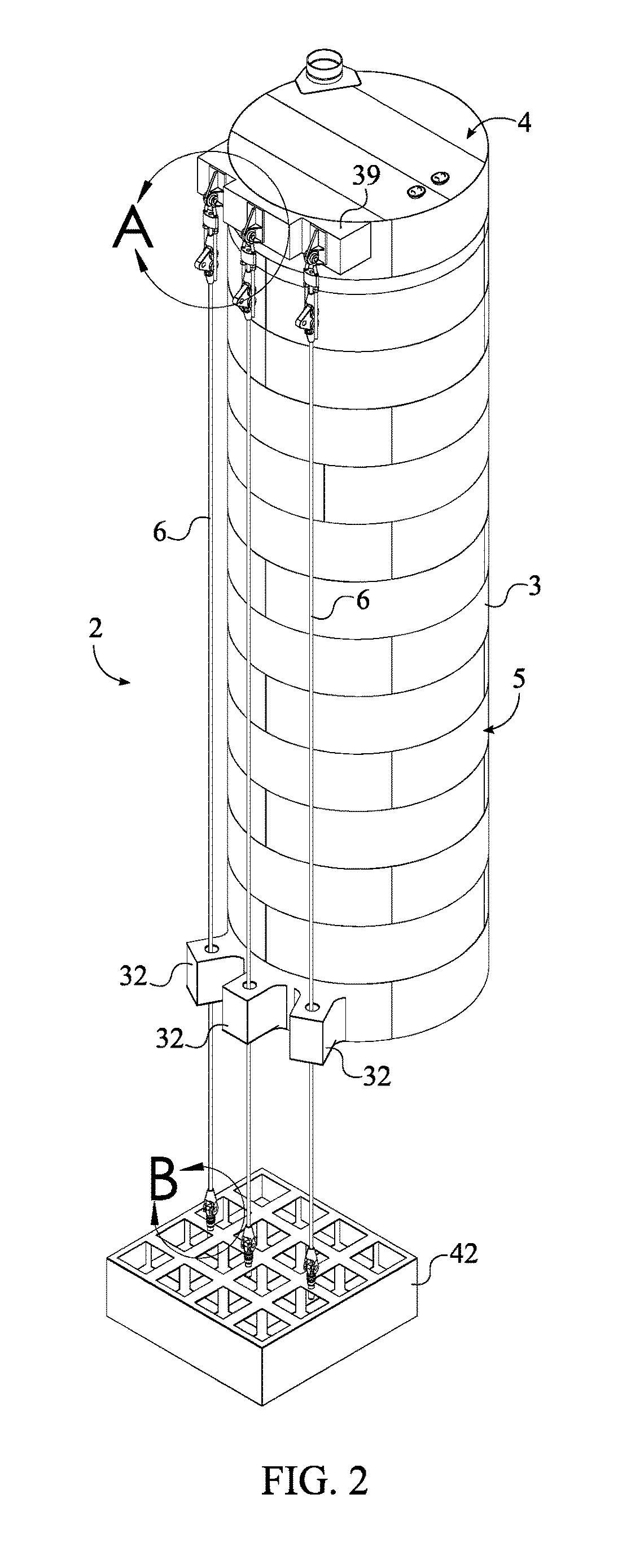
[0030]In the column coupler 7, the column coupler 7 comprises a mounting bracket 8, a first pivot link 9, a second pivot link 10, a first rocker bracket 11, and a second rocker bracket 12. The mooring assembly 6 further comprises a protruding mount 39. In reference to FIGS. 5-6, the protruding mount 39 is connected adjacent to the lateral portion 5, adjacent to the first base 4. The protruding mount 39 is used to provide clearance between the first tendon 27 and the lateral portion 5 of the column 3. The mounting bracket 8 is suspended from the protruding mount 39, adjacent to the lateral portion 5. The mounting bracket 8 acts as a base for the rest of the column coupler 7 to extend from. The first pivot link 9 and the second pivot link 10 are each hingedly connected to the mounting bracket 8. The first pivot link 9 and the second pivot link 10 are positioned opposite to each other along the mounting bracket 8. The first pivot link 9 and the second pivot link 10 are able to rotate a...

third embodiment

[0033]In the column coupler 7, the column coupler 7 comprises a first pivot link 9, a second pivot link 10, a first stabilizing bracket 17, a second stabilizing bracket 18, a first swinging bracket 19, and a second swinging bracket 20. In reference to FIGS. 7A, 7B, 8A, and 8B, the first pivot link 9 is hingedly mounted to the protruding mount 39 and the second pivot link 10 is hingedly mounted to the protruding mount 39, adjacent to the first pivot link 9. The first pivot link 9 and the second pivot link 10 help to stabilize the column 3 in the event that the anchor 42 settles on the seabed or if the column 3 moves. The first stabilizing bracket 17 is hingedly connected to the first pivot link 9, opposite to the protruding mount 39. The first stabilizing bracket 17 is also hingedly connected to the second pivot link 10, opposite to the protruding mount 39. The second stabilizing bracket 18 is connected perpendicular to the first stabilizing bracket 17, in between the first pivot lin...


PUM


Abstract

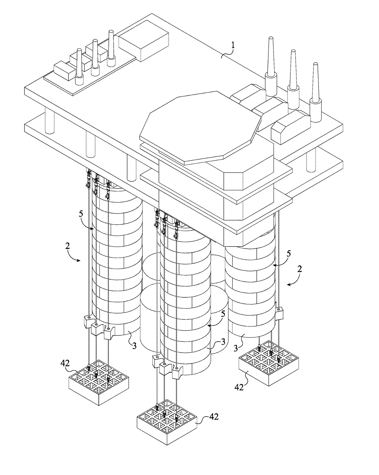
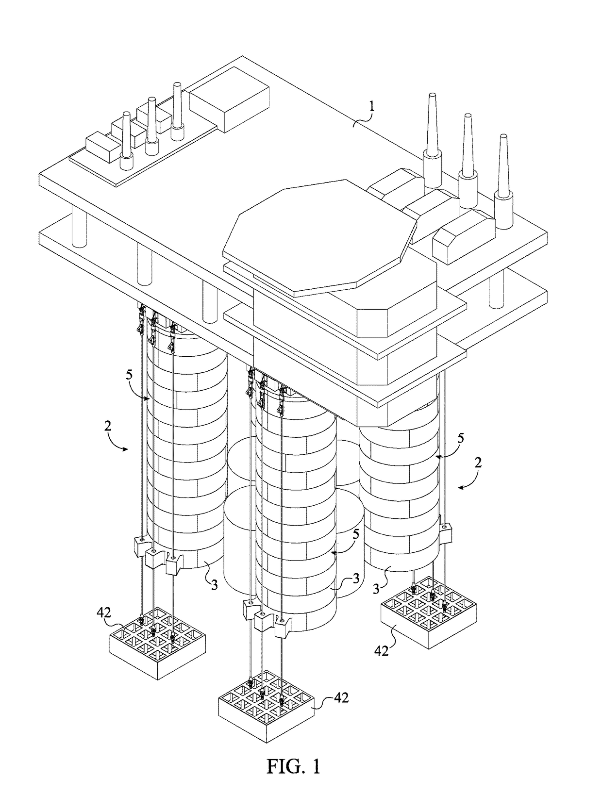
A tension-leg platform anchoring system is used to tether the columns of a floating platform to the seabed and restrict movement of the entire platform. The tension-leg platform anchoring system includes a topside and a plurality of anchored floating supports. The topside provides a deck for supporting workers and equipment. The anchored floating supports are used to keep the topside afloat and limit movement. The anchored floating support includes a column, at least one mooring assembly, and an anchor. The column is connected to the topside and is used to keep the tension-leg platform afloat. The mooring assembly includes a column coupler, a first tendon, and an anchor coupler, which are used together to tether the column to the anchor. The column coupler is tethered to the anchor coupler through the first tendon, which is connected to the column by the column coupler.

Description

[0001]The current application is a continuation-in-part (CIP) application of a U.S. non-provisional application Ser. No. 14 / 853,898 filed on Sep. 14, 2015. The U.S. non-provisional application 14 / 853,898 claims a priority to a U.S. provisional application Ser. No. 62 / 049,410 filed on Sep. 12, 2014. The U.S. non-provisional application 14 / 853,898 was filed on Sep. 14, 2015, while Sep. 12, 2015 was on a weekend.[0002]The current application is further a continuation-in-part (CIP) application of U.S. non-provisional application Ser. No. 14 / 708,165 filed May 8, 2015 which claims priority to U.S. Provisional Patent application Ser. No. 61 / 990,471 filed on May 8, 2014 and U.S. Provisional Patent application Ser. No. 62 / 049,410 filed on Sep. 12, 2014.FIELD OF THE INVENTION[0003]The present invention relates generally to floating offshore structures. More specifically, the present invention is a buoyant semi-submersible offshore platform which uses tendons made from cables or chains instead...

Claims


Application Information

Patent Timeline
Patent Type & Authority Applications(United States)
IPC IPC(8): B63B21/50B63B21/26B63B35/44
CPCB63B21/502B63B2021/505B63B21/26B63B35/44
Inventor TAHAR, ARCANDRA
Owner TAHAR ARCANDRA
Learn More