Wave-power system and method for generating energy at constant rotational speed at variable significant wave heights and periods

a wave power system and wave energy technology, applied in the direction of electric generator control, machines/engines, mechanical equipment, etc., can solve the problems of increasing oil prices, major challenges, and carbon dioxide emissions to be reduced

Inactive Publication Date: 2009-04-28
NOVA OCEANIC ENERGY SYST
View PDF19 Cites 38 Cited by
  • Summary
  • Abstract
  • Description
  • Claims
  • Application Information

AI Technical Summary

Benefits of technology

[0023]It is another principal objective of the present invention to self-adjust the mechanical properties of the wave energy converter (WEC) to take into account the predominant wave frequency over a period of time in a practical way to provide continuous, or multiple level, tuning of the system, and to achieve this inexpensively to allow building commercially viable products.
[0056]The mechanical-type power take-off system is a rotary turbine like system totally enclosed in a steel (or any other suitable material) hull with no external moving parts except fins. The construction of the device is similar to the construction of buoys and small ships and device is thus very robust.

Problems solved by technology

First, there are global warming issues—carbon dioxide emissions must be reduced in many industrialized countries due to ratification of the Kyoto Convention.
Secondly, a dwindling supply of peak oil reserves and growing demand of oil by large nations such as China and India, in addition to growing political tensions in oil producing countries, have increased oil prices tremendously.
Even though wave energy technology development has been going on for a long time, there are major challenges that must be surpassed before this type of technology may be widely used.
Some Prior Art designs have many moving parts that may fail in the long run, requiring frequent maintenance and repair.
Still other systems have very high capital costs due to the construction in open sea of fixed seabed structures.
Other systems have high maintenance costs due to use of ropes and / or pulleys and / or chains and / or springs that may fail in the long run.
In addition, the power quality is low due to the lack of a control system to maintain power quality in a variable resource or the inability to accommodate the variety of wave heights and periods, which occur on an hourly and daily and seasonal basis.
These Prior Art systems have no self-oriented capability to position themselves to absorb the maximum amount of energy from waves and thus optimize energy production, or to position to absorb the minimum amount of energy from waves during storm sea conditions.
In addition, the lack of control systems in the Prior Art limits the ability to vary power generation amount with the size of waves.
Power output is limited to the installed capacity of a generator and its operational limits.
Conversion is limited to one generator and therefore to its operational limits.
In the case of electric power generation, some of the aforementioned Prior Art references confront the power quality in a variable resource (waves of variable significant wave height and wave periods) by maintaining constant speed of the main shaft through mechanical brakes and or increasing the load of the generators (electromagnetic braking); however all of those systems have limitations in the large range of waves of variable significant wave height and wave periods.
This would make the rotational speed transmitted to the drive shaft by the float hit by the higher wave greater than that transmitted by the float hit by the low wave, rendering the energy generated by the float hit by the low wave useless (i.e., this energy would not be transmitted to the drive shaft).
Therefore, it is probable that the energy generated by this device will be always lower than that possibly generated by its total floating capacity.
However, to effectuate the called for proposed adjustments to the mechanical properties of a WEC is problematic since there is no practical way to provide continuous, or multiple level, tuning of the system”.
In the same International Patent Application it is mentioned, “In all of known proposed wave energy converter efficiency-boosting schemes, the energy storage and / or tuning components are large and / or expensive making it difficult and / or expensive to produce commercially viable products.”

Method used


Image

  • Wave-power system and method for generating energy at constant rotational speed at variable significant wave heights and periods
  • Wave-power system and method for generating energy at constant rotational speed at variable significant wave heights and periods
  • Wave-power system and method for generating energy at constant rotational speed at variable significant wave heights and periods

Examples


Embodiment Construction

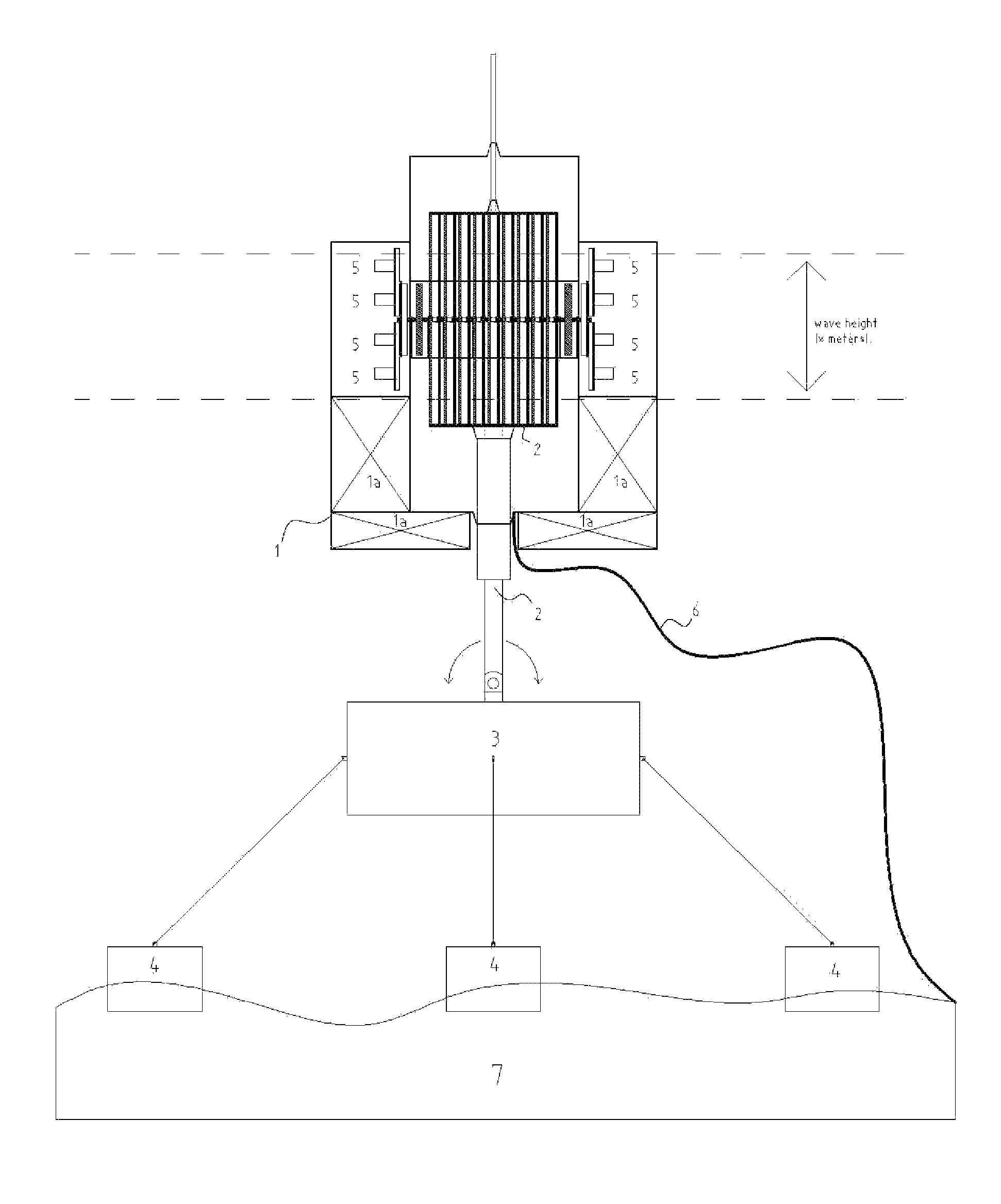
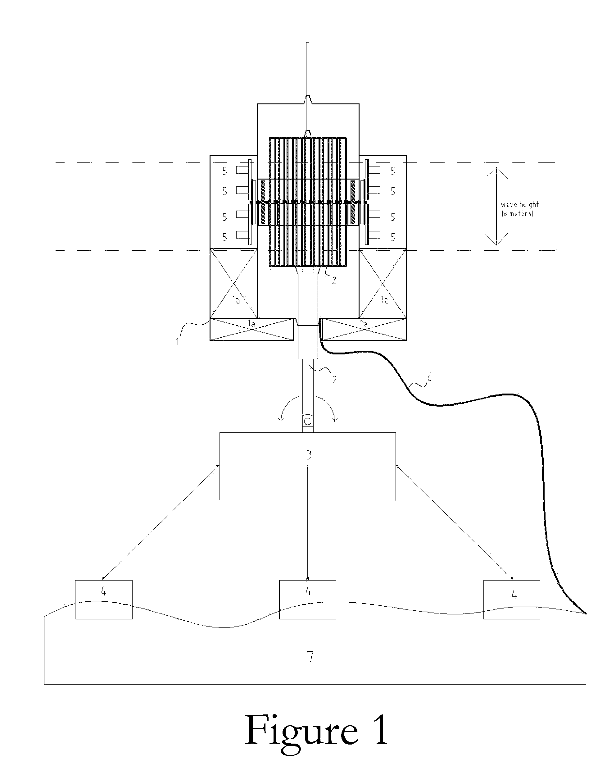
[0094]The following Figures are not to scale. The actual dimension and / or shape of each of the device components may vary. Only important details of the device are shown, however one of ordinary skill in the art can appreciate how the overall device may be constructed, without undue experimentation. The device may be constructed using standard ship building methods and materials or any appropriate materials and methods to allow efficiency and survivability.

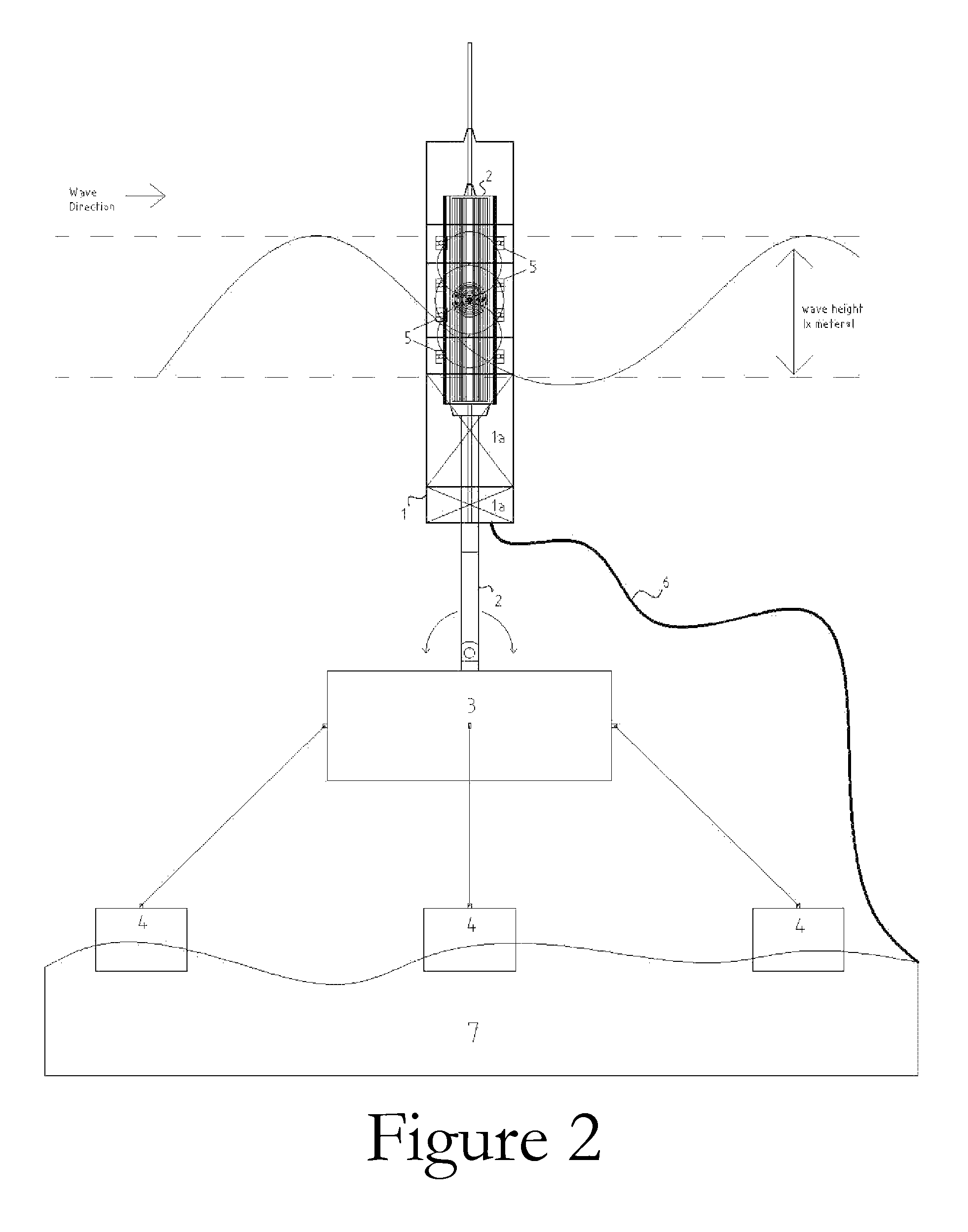
[0095]FIG. 1 is a general front view of the wave energy converter. FIG. 2 is a general side view of the wave energy converter of FIG. 1. Note the movement and direction of the waves as illustrated in FIG. 2. Referring to FIGS. 1 and 2, the apparatus is composed of a water-tight hull structure 1 which acts as a floating portion of the device and moves up and down with passing waves. Hull structure 1 has ballast tanks 1a in the lower part. A fork-like rod system 2 acts as the fixed member of the device, not moving up and down with p...


PUM


Abstract

A wave energy conversion system or device is provided which includes a hull that serves as a float, moving up and down with incoming waves. The power take-off system contained within the hull comprises a longitudinal main rotary shaft upon which a series different diameter sets of dual same-diameter pinions interact with the main rotary shaft through their corresponding freewheels. This interaction only allows the main rotary shaft to rotate in only one direction. A fork-like rod system member that is either fixed directly to a base on the seabed or to a supporting underwater taut moored floating platform. This fork-like rod system member has an alternate rod in permanent contact with each pinion (two rods per each set of dual same-diameter pinions). The device also is capable of self-adjusting its mechanical properties and orientation to take into account the predominant wave frequency and direction over a period of time in a practical way to provide continuous, or multiple level, tuning of the system and is self-orienting for maximum and minimum energy absorption depending on sea conditions.

Description

CROSS-REFERENCE TO RELATED APPLICATIONS[0001]The present application claims priority from Provisional U.S. Patent Application Ser. No. 60 / 813,762, filed on Jun. 14, 2006, and incorporated herein by reference.FIELD OF THE INVENTION[0002]The present invention relates to heaving-buoy wave-energy converters. In particular, the present invention is directed toward a multiple double-action power take-off system utilizing a large range of significant wave heights and wave periods. The invention is a converter that changes random movement of waves into high-speed rotational movement. Also, the invention describes a method for maintaining a constant rotational speed of flywheels and therefore constant electric generating power or any other use of flywheel power may be made (rotary pumps, desalinization, and other equivalent devices that utilize rotary motion to function) at a large range of significant wave heights and wave periods.BACKGROUND OF THE INVENTION[0003]There are several reasons t...

Claims


Application Information

Patent Timeline
Patent Type & Authority Patents(United States)
IPC IPC(8): F03B13/12F03C99/00
CPCF03B13/186F05B2260/4031F05B2260/503Y02E10/38Y02E10/30
Inventor ATILANO MEDINA, ALVARO JOSEUZCATEGUI TRINKL, RAFAEL
Owner NOVA OCEANIC ENERGY SYST
Why Eureka
Try Eureka