Control system for hybrid vehicle

Active Publication Date: 2017-04-27
TOYOTA JIDOSHA KK
View PDF0 Cites 15 Cited by
  • Summary
  • Abstract
  • Description
  • Claims
  • Application Information

AI Technical Summary

Benefits of technology

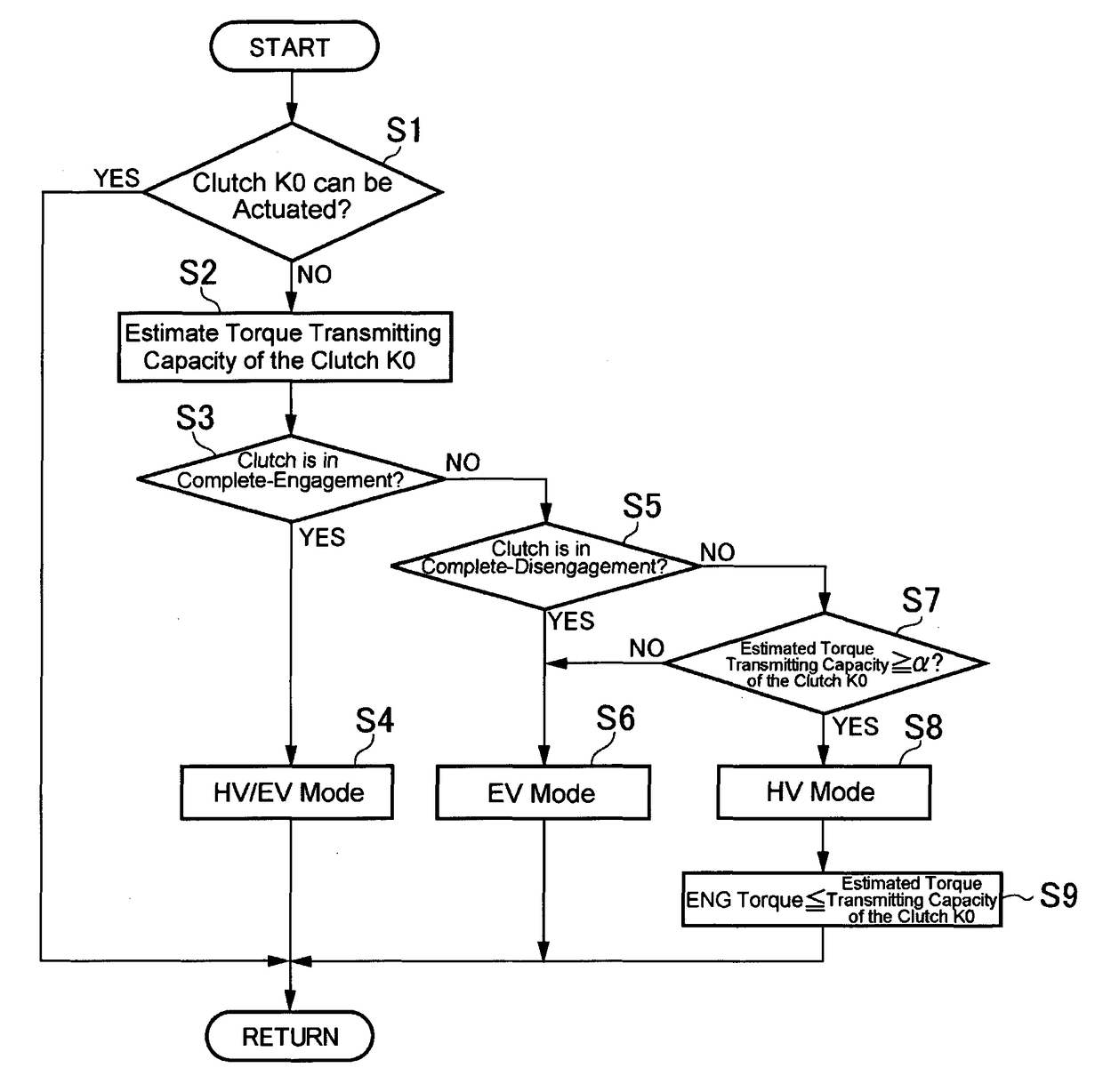
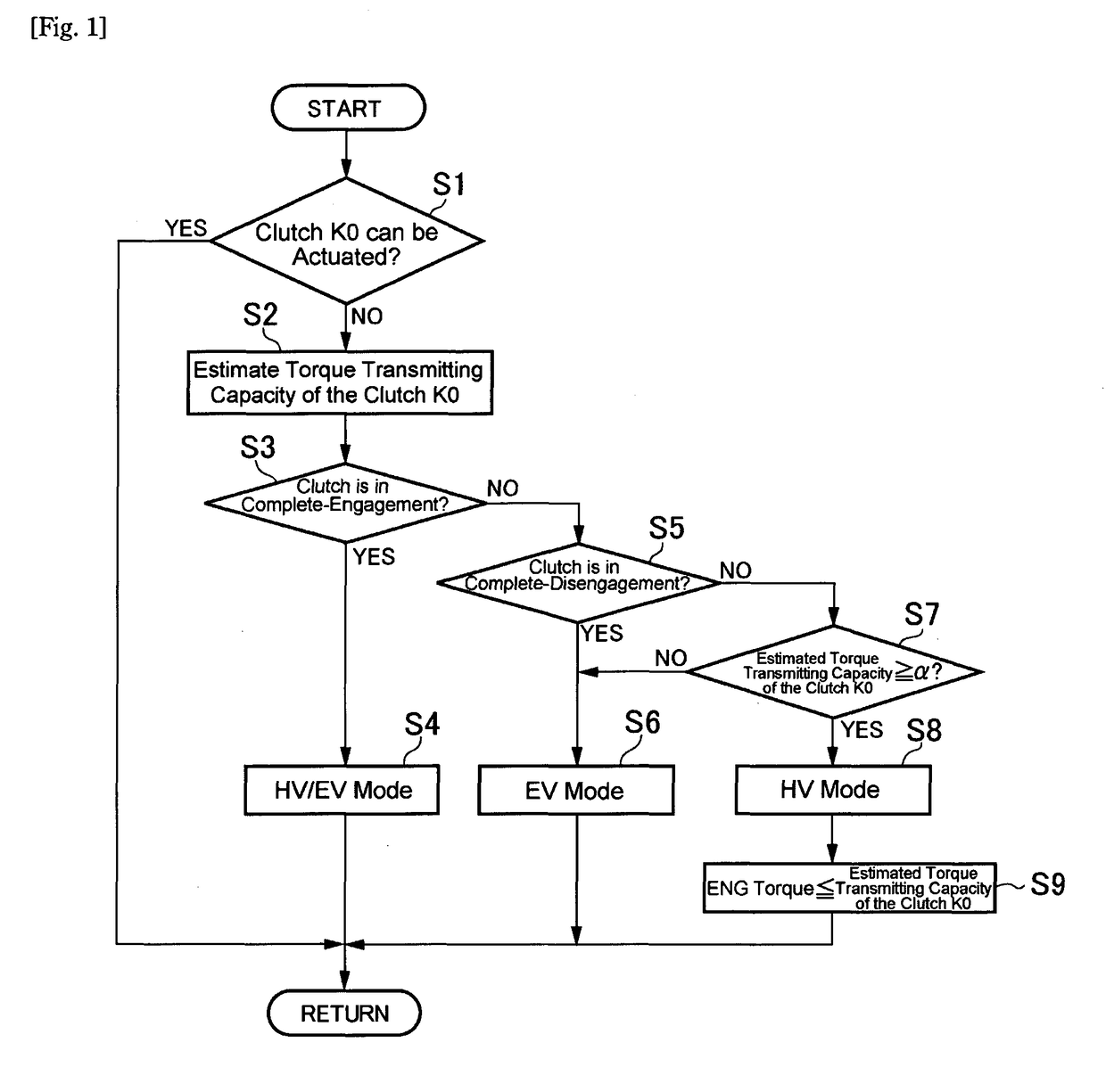
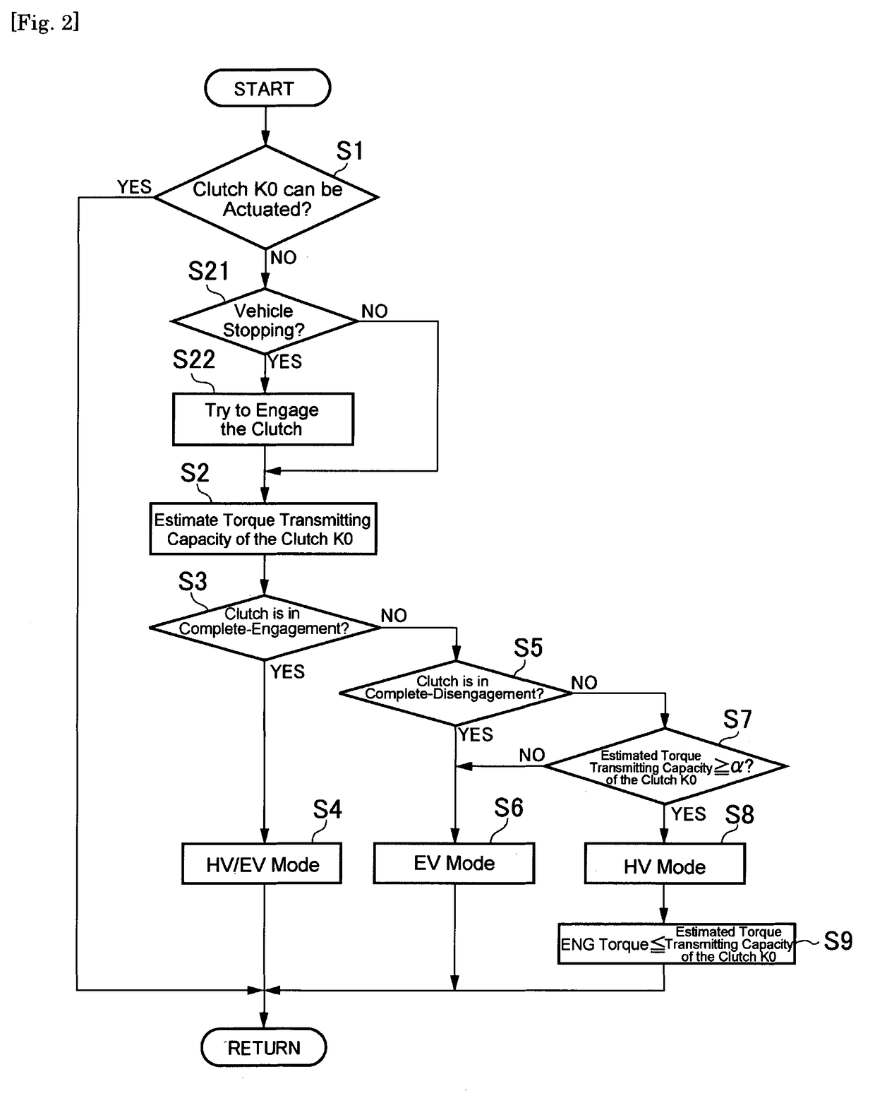
[0015]Thus, in case the torque transmitting capacity of the engagement device cannot be altered by failure and the estimated torque transmitting capacity of the engagement device in trouble is larger than a first threshold value, the first drive mode is selected to power the vehicle by the engine. In this case, output torque of the engine is reduced to be smaller than the estimated torque transmitting capacity of the engagement device. According to the present invention, therefore, the vehicle is allowed to be powered by the engine without worsening a slippage of the engagement device in trouble so that the battery can be charged without consuming electricity. For this reason, the vehicle is allowed to travel over a long distance in the event of failure of the engagement device. In addition, in case the first drive mode still can be selected in the event of failure of the engagement device, sufficient driving force and braking force can be ensured in comparison with those under the second drive mode.
[0016]According to another aspect of the present invention, the control system tries to bring the engagement device into engagement again during the vehicle is stopping in the event of failure of the engagement device. Therefore, the torque transmitting capacity of the engagement device may possibly be increased to a level sufficient to crank the engine so that the opportunity to establish the first drive mode can be increased. For this reason, the electric power of the battery may be saved so that a traveling distance of the vehicle may possibly be extended even if the engagement device is still in trouble. In addition, since such attempt of engagement of the engagement device is ex

Problems solved by technology

In the hybrid vehicle of this kind, if the vehicle is powered only by the motor under a situation that a torque transmission of the engine and the motor cannot be interrupted due to failure, a power loss will be caused to rotate the engine passively.
As a result, an elec

Method used


Image

  • Control system for hybrid vehicle
  • Control system for hybrid vehicle
  • Control system for hybrid vehicle

Examples


Embodiment Construction

[0031]The vehicle control system of preferred embodiment is applied to a vehicle having an engine and a motor each generating torque to transmit to driving wheels, and an engagement device that interrupts the torque transmissions both between the engine and the motor and between the engine and the driving wheels by disengaging. A preferred example of the vehicle to which the preferred embodiment is applied is illustrated in FIG. 4. The vehicle shown in FIG. 4 is a hybrid vehicle comprised of an engine (ENG) 1, and motors 2 (MG1) and 3 (MG2). The vehicle shown in FIG. 4 can be driven not only by the engine 1 but also by a combination of the engine 1 and the motor 2 (3). In addition, the vehicle can also be driven only by the motor 3. The motor 2 and 3 are adapted to regenerate energy while the vehicle is running. When the vehicle is driven by the motor 3, the engine 1 is allowed to be stopped and restarted. Under EV mode in which the motor 3 is used as a prime mover for driving the v...


PUM


Abstract

A control system for hybrid vehicle for extending a possible travelling distance of the vehicle in the event of clutch failure is provided. The control system is configured to select a first drive mode in which the vehicle is powered by an engine in case an estimated torque transmitting capacity of the clutch in trouble is larger than a first threshold value, and to select a second drive mode in which the vehicle is powered by a motor in case the estimated torque transmitting capacity of the clutch in trouble is smaller than the first threshold value. The control system is further configured to reduce an engine torque to be smaller than the estimated torque transmitting capacity of the clutch in case the first drive mode is selected.

Description

TECHNICAL FIELD[0001]The present invention relates to a control system for a hybrid vehicle comprising an engine, a motor, and an engagement device for selectively interrupting torques of the engine and the motor transmitted to driving wheels.BACKGROUND ART[0002]JP-A-08-295140 describes a hybrid vehicle in which torques of an engine and a first motor is delivered to driving wheels. The hybrid vehicle is provided with a differential gear unit including a first rotary element connected to an output shaft through a clutch, a second rotary element connected to the first motor, and a third rotary element connected to the driving wheels, and further provided with a second motor generating a torque delivered to the driving wheels from downstream side of the third rotary element. In the hybrid vehicle taught by JP-A-08-295140, a drive mode can be selected from a hybrid mode in which the clutch is brought into engagement to transmit torques of the engine and the first motor to the driving wh...

Claims


Application Information

Patent Timeline
IPC IPC(8): B60W20/50B60W10/02B60W10/06F16H48/10B60W10/26B60K6/445B60W20/40B60K6/387B60W10/08B60L50/16
CPCB60W20/50B60K6/387B60W10/02B60W10/06B60W10/08B60W10/26Y10S903/946B60W20/40F16H48/10B60W2510/0275B60W2510/242B60W2510/08B60Y2300/18008B60K6/445B60K2006/4825B60W20/13B60W50/029B60W50/032B60W2050/022B60W2050/0297B60W2510/244Y02T10/62
Inventor HATA, KENSEIIWASE, YUJISUZUKI, YOSUKEKATO, KOICHINOBUYASU, SEITAROMOTEKI, TARO
Owner TOYOTA JIDOSHA KK
Why Eureka
Try Eureka