Image display device

a display device and image technology, applied in the field of image display devices, can solve the problems of reducing visual perceptibility and difficulty in keeping the pupil of the user fixed, and achieve the effect of excellent see-through characteristics and high visual perceptibility

Inactive Publication Date: 2017-04-27
SEIKO EPSON CORP
View PDF5 Cites 12 Cited by
  • Summary
  • Abstract
  • Description
  • Claims
  • Application Information

AI Technical Summary

Benefits of technology

[0025]Therefore, an image display device that realizes both excellent see-through characteristics and high visual perceptibility can be obtained.

Problems solved by technology

However, it is difficult to keep the pupil of a user fixed when an image is visually perceived.
As a result, missing in the field of vision (vignetting) occurs in the display of an image and the background, etc., which makes it impossible for the user to visually perceive the image as supposed to, resulting in a decrease in visual perceptibility.

Method used


Image

  • Image display device
  • Image display device
  • Image display device

Examples


first embodiment

[0036]First of all, an image display device according to a first embodiment will now be explained.

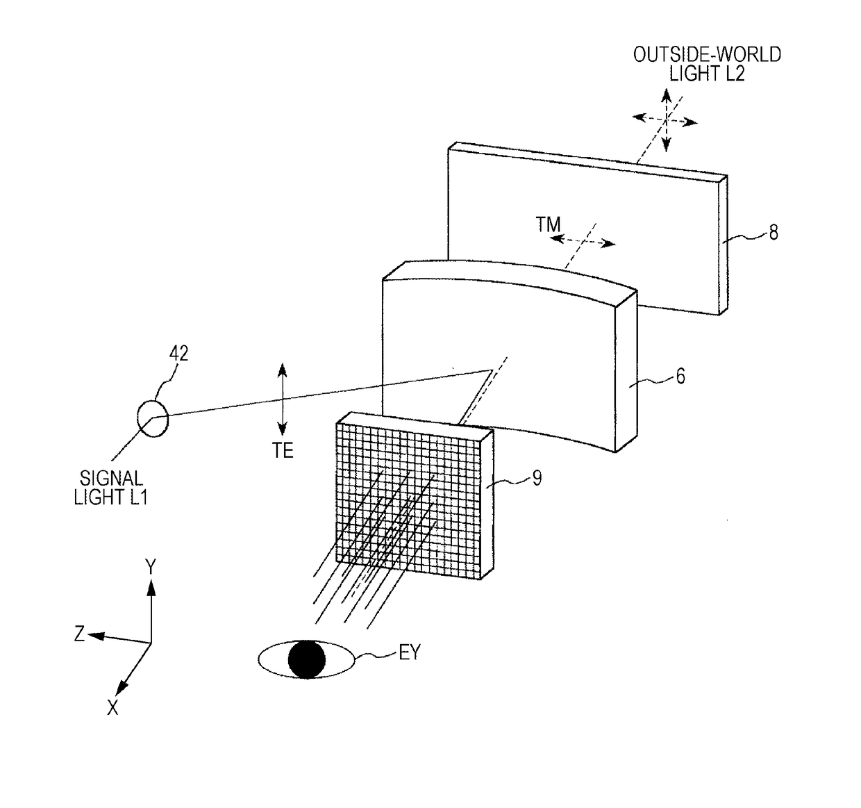
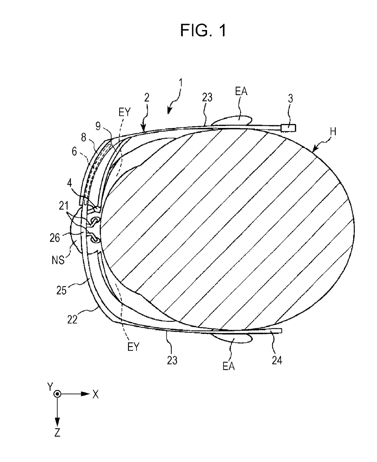
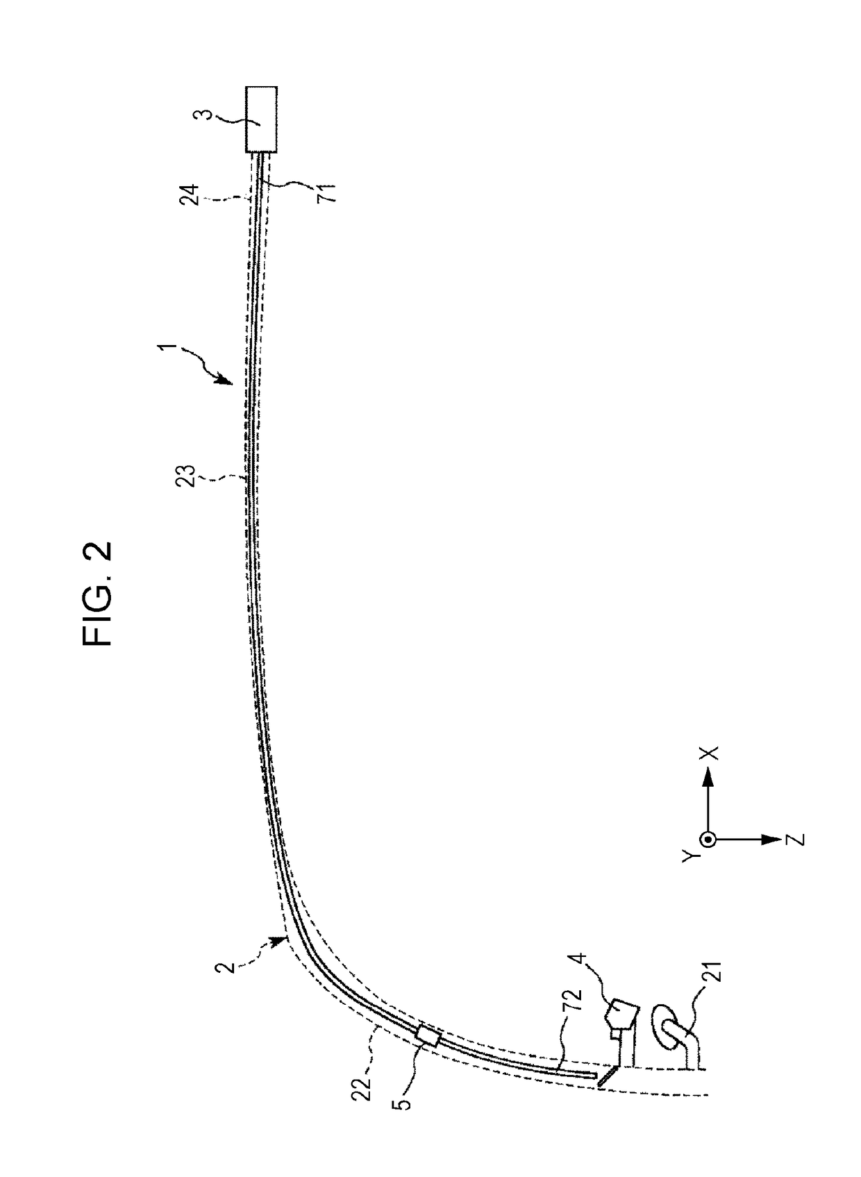
[0037]FIG. 1 is a diagram that illustrates a schematic structure of an image display device according to a first embodiment (head-mounted display). FIG. 2 is a partial enlarged view of the image display device illustrated in FIG. 1. FIG. 3 is a schematic structure view of a signal generation unit of the image display device illustrated in FIG. 1. FIG. 4 is a diagram that illustrates a schematic structure of a light scan unit included in a scan light emission unit illustrated in FIG. 1. FIG. 5 is a diagram for schematically explaining the functional operation of the image display device illustrated in FIG. 1.

[0038]In FIG. 1, for the purpose of easier description, X, Y, and Z axes are shown as three axes that are orthogonal to one another. The head of the axial arrow in the illustration is defined as “+ (plus)”, and the tail thereof is defined as “− (minus)”. The direction parallel to the...

second embodiment

[0140]Next, an image display device according to a second embodiment will now be explained.

[0141]FIG. 7 is a diagram for schematically explaining the functional operation of an image display device according to a second embodiment. FIG. 8(a) is a Y-directional view of the diffracting optical unit 9 illustrated in FIG. 7. FIG. 8(b) is an X-directional view of the diffracting optical unit 9.

[0142]In the explanation of the second embodiment below, the points of difference from the foregoing first embodiment are mainly explained, and an explanation is omitted for the same matters. In the drawings, the same reference signs are assigned to the same matters as those of the foregoing embodiment.

[0143]The diffracting optical unit 9 according to the second embodiment is the same as the diffracting optical unit 9 according to the first embodiment except for the difference in the grating pattern of each diffraction grating.

[0144]That is, in the diffracting optical unit 9 according to the presen...

third embodiment

[0151]Next, an image display device according to a third embodiment will now be explained.

[0152]FIG. 9 is a diagram that illustrates an image display device according to a third embodiment (head-up display). In FIG. 9, for the purpose of easier description, X, Y, and Z axes are shown as three axes that are orthogonal to one another. The head of the axial arrow in the illustration is defined as “+ (plus)”, and the tail thereof is defined as “− (minus)”. The direction parallel to the X axis is hereinafter referred to as “X-axis direction”. The direction parallel to the Y axis is hereinafter referred to as “Y-axis direction”. The direction parallel to the Z axis is hereinafter referred to as “Z-axis direction”.

[0153]In the explanation of the third embodiment below, the points of difference from the foregoing first and second embodiments are mainly explained, and an explanation is omitted for the same matters. In the drawings, the same reference signs are assigned to the same components...


PUM


Abstract

Provided is an image display device that attains see-through characteristics and visual perceptibility with a simple structure.
An image display device includes a frame, a signal generation unit (light source unit) that generates signal light L1 that is a TE wave, a scan light emission unit that is provided with a light scan unit 42 (light scanner) that scans the signal light L1, a reflection unit 6 (reflecting optical unit) that reflects the signal light L1 scanned by the light scan unit 42; a diffracting optical unit 9 that includes a pair of diffraction gratings whose grating patterns are equivalent to each other and diffracts the signal light L1 reflected at the reflection unit 6; and a polarizing plate 8 (polarization selection unit) that is located at an opposite side in relation to the diffracting optical unit 9 with respect to the reflection unit 6 and allows outside-world light L2 that is a TM wave to pass toward the reflection unit 6, wherein the diffracting optical unit 9 diffracts the signal light L1 and does not diffract the outside-world light L2. The signal light L1 is split into plural beams at the diffracting optical unit 9 to enter the eye EY of a user.

Description

CROSS-REFERENCE TO RELATED APPLICATIONS[0001]This application is a U.S. National Phase Application under 35 U.S.C. 371 of International Application No. PCT / JP2015 / 002943, filed on Jun. 11, 2015 and published in Japanese as WO 2016 / 002138 on Jan. 7, 2016. This application claims priority to Japanese Patent Application No. 2014-135098, filed on Jun. 30, 2014. The entire disclosures of the above applications are incorporated herein by reference.TECHNICAL FIELD[0002]The present invention relates to an image display device.BACKGROUND ART[0003]A head-mounted display (HMD) is known as a display device that enables a user to visually perceive an image by directly irradiating the retina of the pupil with laser light.[0004]In general, a head-mounted display includes a light emitting device that emits light and a scanning means that changes a light path so that the emitted light will be scanned on the retina of a user. Such a head-mounted display enables the user to visually perceive, for exam...

Claims


Application Information

Patent Timeline
Patent Type & Authority Applications(United States)
IPC IPC(8): G02B27/01G02B27/42G02B5/18G02B27/28
CPCG02B27/0101G02B27/283G02B27/4227G06T11/60G02B5/1823G02B2027/0125G02B2027/013G02B27/4261B60K35/00H04N5/64G02B27/0081G02B27/0172
Inventor YOKOYAMA, OSAMU
Owner SEIKO EPSON CORP
Why Eureka
Try Eureka