
Maintenance unit and liquid ejecting apparatus

a technology of maintenance unit and liquid ejector, which is applied in the direction of printing, other printing apparatus, etc., can solve the problem of extra maintenance effor

Active Publication Date: 2017-05-11
SEIKO EPSON CORP
View PDF16 Cites 2 Cited by
  • Summary
  • Abstract
  • Description
  • Claims
  • Application Information

AI Technical Summary

Benefits of technology

The invention provides a liquid ejecting apparatus and maintenance unit that are easy to separate and replace. The apparatus has a common supporting member for the liquid receiving and discharging portions, and a positioning portion in the maintenance unit for easy positioning of the waste liquid container. The apparatus also has an insertion / removal pathway for easy maintenance, and a mounting portion for detachable mounting of the waste liquid container. Additionally, the invention includes a structure that absorbs positional deviation between the mounting portion and the liquid ejecting apparatus body to ensure electrical connection between them. The invention also prevents contact between the liquid ejecting apparatus and the discharging portion during maintenance.

Problems solved by technology

Moreover, when replacing either of the maintenance unit and the waste liquid container, extra effort in maintenance was required as it was necessary to remove the tube after releasing the positioning, on the liquid ejecting apparatus, of the part to be replaced.

Method used


Image

  • Maintenance unit and liquid ejecting apparatus
  • Maintenance unit and liquid ejecting apparatus
  • Maintenance unit and liquid ejecting apparatus

Examples


Embodiment Construction

[0032]Hereinafter, embodiments of a maintenance unit and a liquid ejecting apparatus according to the invention will be described while referencing the drawings. In the drawings used in the following description, the scale of each constituent is appropriately adjusted to a recognizable size.

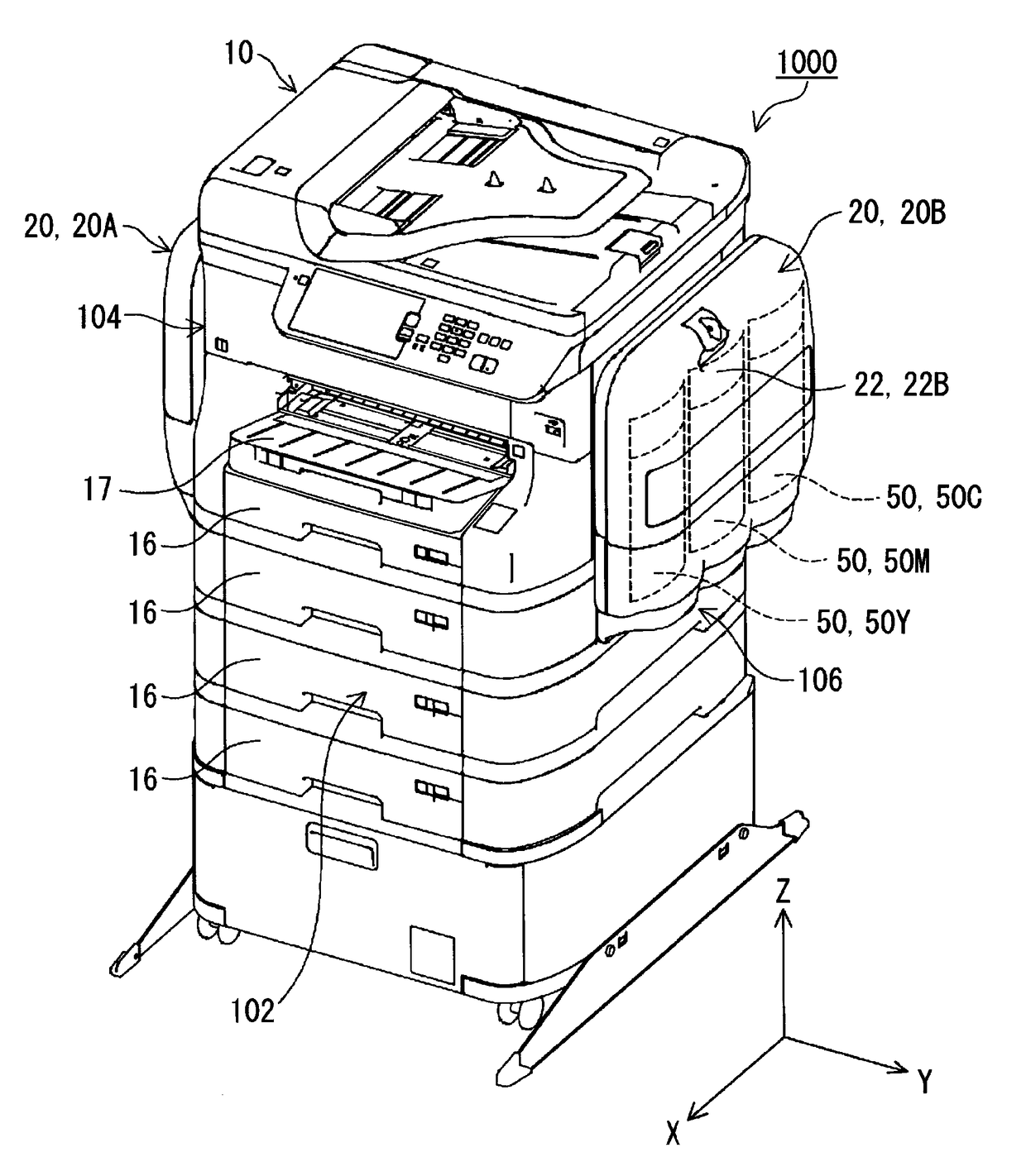
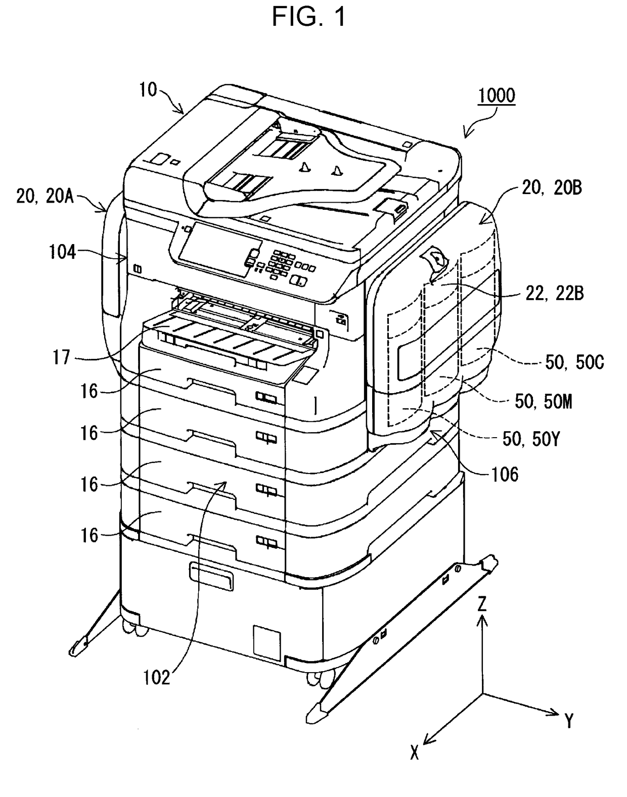
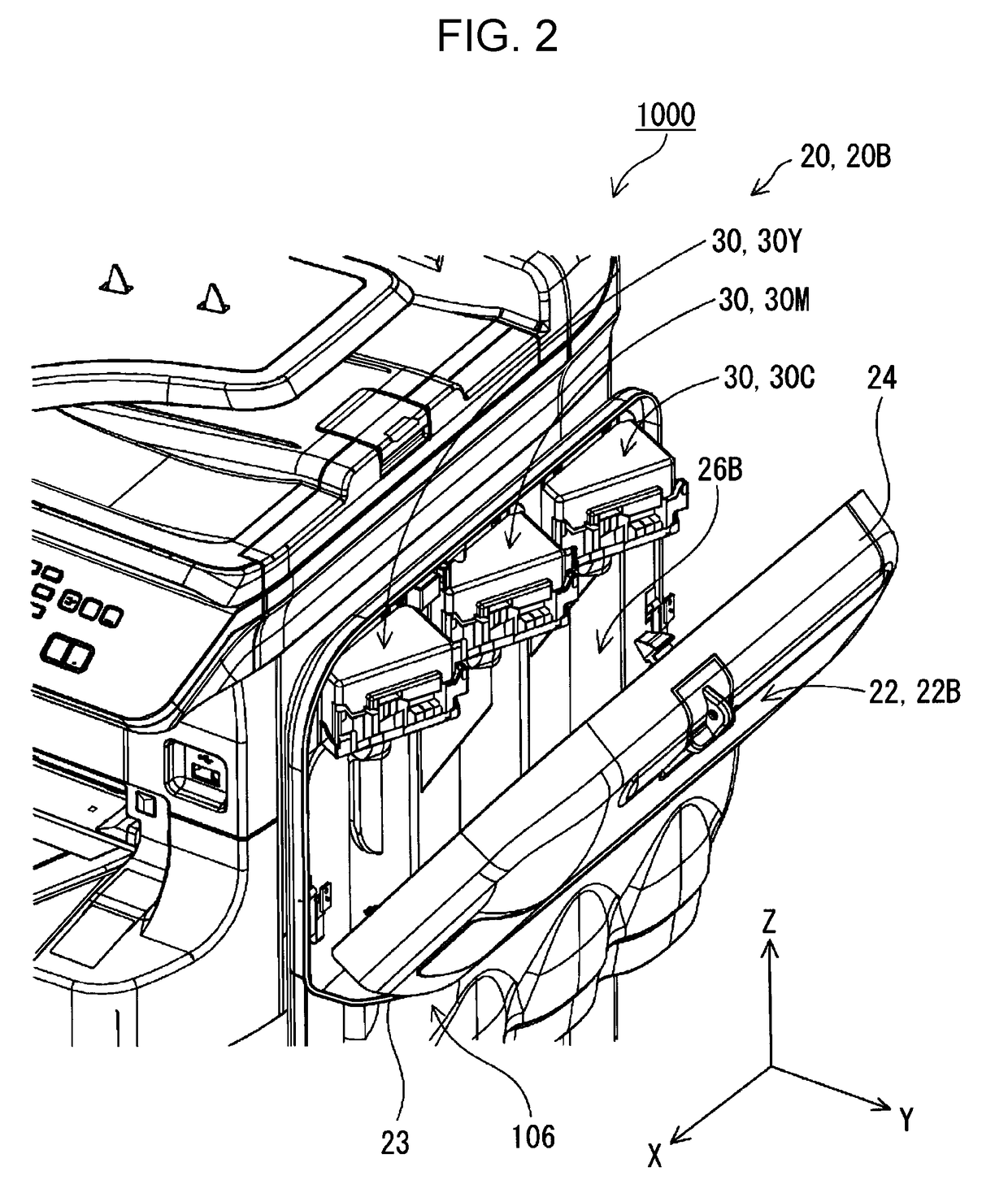
[0033]FIG. 1 is a perspective view illustrating an overall appearance of a liquid ejecting apparatus 1000 according to an embodiment of the invention. FIG. 2 is a perspective view illustrating the liquid ejecting apparatus 1000 according to an embodiment of the invention, in a state where a side portion is opened.

[0034]Note that, in FIGS. 1 and 2, an XYZ orthogonal coordinate system is set. In the liquid ejecting apparatus 1000, a front / rear direction is the X-axis direction, a direction orthogonal to the X-axis direction in the horizontal plane is the Y-axis direction (horizontal direction), and a direction (vertical direction) orthogonal to each of the X-axis direction and the Y-axis direction ...


PUM


Abstract

A maintenance unit including a liquid receiving portion that receives liquid, a discharging portion that discharges the liquid received by the liquid receiving portion into a waste liquid container, a common supporting member that supports the liquid receiving portion and the discharging portion, and a positioning portion that positions the waste liquid container.

Description

BACKGROUND[0001]1. Technical Field[0002]The present invention relates to a maintenance unit and a liquid ejecting apparatus.[0003]2. Related Art[0004]Ink jet printers have been known as an example of a liquid ejecting apparatus that perform printing on paper (recording media) by ejecting ink (liquid) from an ink jet head (liquid ejecting head). For example, JP-A-2007-296757 describes a liquid ejecting apparatus provided with a maintenance unit that discharges thickened liquid, air bubbles, and foreign substances from the liquid ejecting head along with the liquid for the purpose of resolving ejecting failures of the liquid from the liquid ejecting head.[0005]JP-A-2007-296757 describes technique aimed at enabling maintenance work to be easily and inexpensively performed on a maintenance unit. The maintenance unit described in JP-A-2007-296757 includes a unit frame that holds a pump, and a pump tube that is provided for the pump and connected to a waste liquid tank (waste liquid conta...

Claims


Application Information

Patent Timeline
IPC IPC(8): B41J2/165B41J2/17
CPCB41J2/1721B41J2/16511B41J2/16508B41J2/16523B41J2/175B41J2/17509B41J29/13
Inventor OTAGIRI, YOSHIHIROSHIMOMURA, MASAKI
Owner SEIKO EPSON CORP
Learn More