Display device with backlit multiple symbols

Active Publication Date: 2017-05-11
PREH
View PDF2 Cites 0 Cited by
  • Summary
  • Abstract
  • Description
  • Claims
  • Application Information

AI Technical Summary

Benefits of technology

The invention is a display device with a single surface that has several segments that can be backlit up. These segments are arranged in a way that if parts of them are lit up together, a different symbol is depicted by each segment. To prevent interference from the separation of the segments, a diffuser layer is used. The device consists of several layers of transparent or translucent material that are stacked together. The layers are designed so that the light of one light source is transmitted to at least one segment of the associated symbol. This design is simple and cost-effective. Its technical effects are improved clarity and depth of symbol depiction, as well as reduced interference between segments.

Problems solved by technology

However, the individual segments are, for example, not necessarily configured in a uniform manner.

Method used


Image

  • Display device with backlit multiple symbols
  • Display device with backlit multiple symbols
  • Display device with backlit multiple symbols

Examples


first embodiment

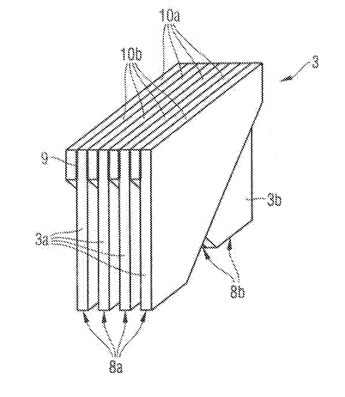
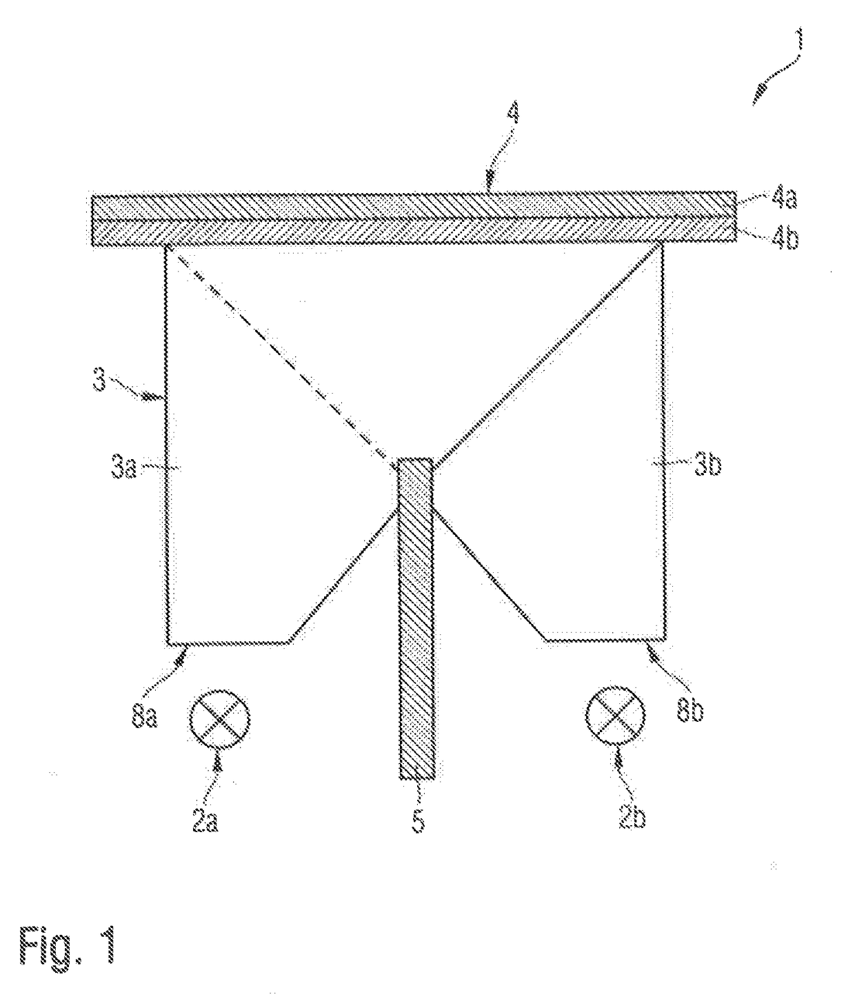
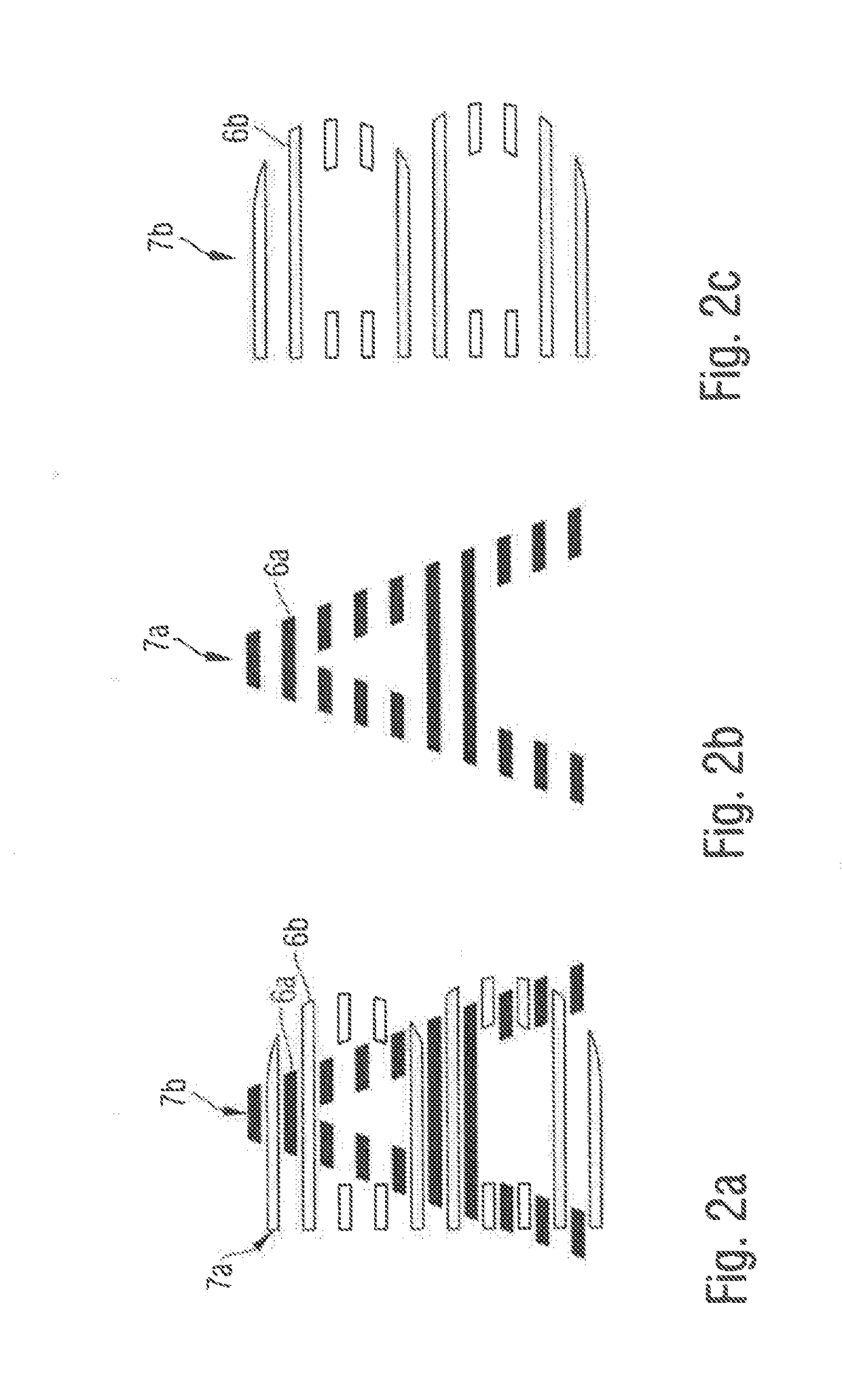
[0032]FIG. 1 shows the display device 1 according to the invention in a sectional view. It has a display surface 4 facing towards an observer, possibly also the operator, who is not shown. This display surface 4 is defined by an external display layer 4, which in this case is colored in a diffuse manner and thus translucent. In order to depict different symbols on this display surface 4, a masking layer 4b is provided, which defines several light-transmissive segments, which cannot be seen in the perspective chosen in FIG. 1 and which are explained below based on the FIGS. 2a to 2c. Two light sources 2a and 2b, which are disposed spaced apart from each other and equidistant from the display surface 4, and which are each provided for alternatingly backlighting one of the two symbols that are to be depicted by backlighting subsets of segments, are disposed on the side of the display surface 4 facing away from the operator. A layer structure 3 of alternatingly disposed light transmitti...

third embodiment

[0037]the layer structure 3 shown in FIG. 5 has congruently stacked light transmitting layers 3a and 3b, with the respective association with the light sources 2a and 2b of FIG. 1 resulting solely from the respective narrow side portions facing towards and adjacent to the light sources either being masked, like the narrow side portions 8a′ and 8b′, or non-masked, like the narrow side portions 8a and 8b. The V-shaped incision 11, which is provided centrally between the narrow sides 8a′, 8b′ or 8a, 8b that are differently coated or uncoated in accordance with the association with the light sources, results in a guidance of the light in the respective light transmitting layers 3a and 3b.


PUM


Abstract

A display device is provided. The display device comprises a display surface with several segments that can be backlit, which are configured in such a way that, if subsets of the segments are backlit together, a different one of several symbols is in each case depicted by the display surface, a number of light sources corresponding to the number of symbols, a layer structure of several flat light transmitting layers made of a transparent or translucent material, preferably plastic, wherein the light transmitting layers are stacked with the main surfaces facing each other and are in each case configured in such a way that, primarily, light of exactly one of the light sources is transmitted from a narrow side of the light transmitting layer provided for light entrance to another narrow side of the light transmitting layer as a light exit to at least one segment of the associated symbol.

Description

CROSS-REFERENCE TO RELATED APPLICATION[0001]This application claims foreign priority of German application Serial Numbers DE 10 2015 119 107.5 filed on Nov. 6, 2015 and DE 10 2016 104 708.2 filed on Mar. 15, 2016, the entireties of which are incorporated herein by reference.BACKGROUND OF THE INVENTIONField of the Invention[0002]The invention relates to a display device for depicting several, preferably different, symbols on a display surface.[0003]It is known to realize this object by means of an electronic display, such as a liquid crystal display. This approach is comparatively complex and expensive; in particular, despite immense developments in this field, the quality of depiction is still strongly dependent on the ambient conditions and the viewing angle, and a comparatively large effort must be made in order to prevent the symbol from “burning in” in the case of a small variety of depictions and a long displaying duration.[0004]Against this background, there is a demand for a ...

Claims


Application Information

Patent Timeline
IPC IPC(8): F21V8/00
CPCG02B6/0076G02B6/0035G02B6/0068G02B6/006
Inventor KRAMLICH, ANDREAS
Owner PREH
Why Eureka
Try Eureka