Metal cutting machine tool

Inactive Publication Date: 2016-12-08
GROB WERKE & K G
View PDF0 Cites 0 Cited by
  • Summary
  • Abstract
  • Description
  • Claims
  • Application Information

AI Technical Summary

Benefits of technology

The patent is about a new system that allows for the removal of the need for manual displacement of a workpiece or pallet and the use of a separate drive for this purpose. The system uses a motor spindle to provide the necessary power or movement for holding and fixing the workpiece or pallet, eliminating the need for an additional drive. It also improves efficiency, reduces costs, and removes defect sources.

Problems solved by technology

However, it has been found, that the manual displacement causes higher costs and susceptibility to errors and that the use of a special drive for displacing the work piece of pallet causes high costs.

Method used


Image

  • Metal cutting machine tool
  • Metal cutting machine tool
  • Metal cutting machine tool

Examples


Embodiment Construction

[0049]In figures, same or corresponding elements are provided with the same references, respectively, and are not newly described, if not necessary. The disclosure contained in the whole description may be transferred analogously to equal parts with same references or same component definitions. The positional data chosen in the description, such as up, down, side, etc., also refer to the instant represented figure and have to be transferred, analogously, to the new position, in case of a change of position. Moreover, also individual features or feature combinations from the different exemplary embodiments shown and described may represent independent inventive solutions or solutions according to the invention.

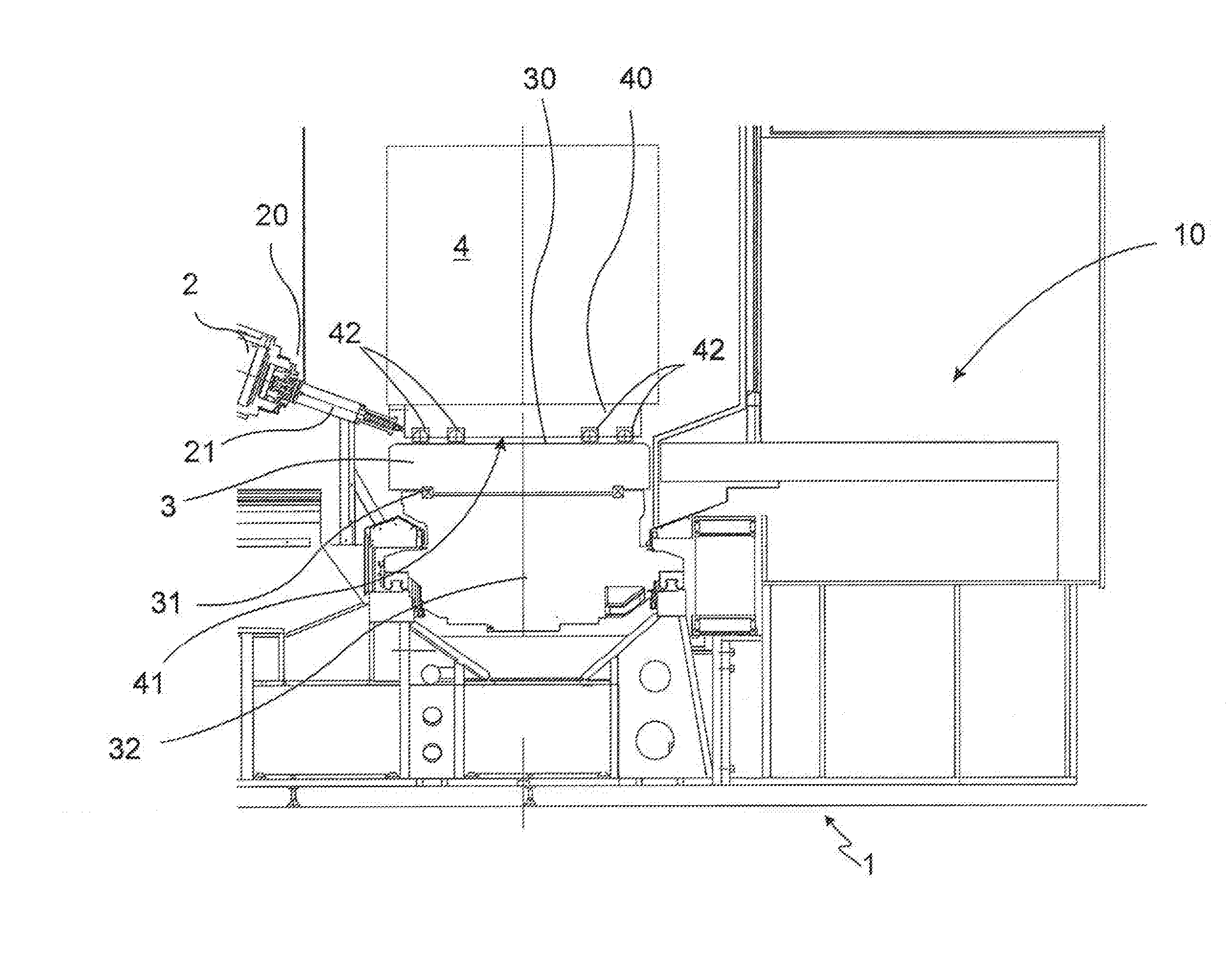
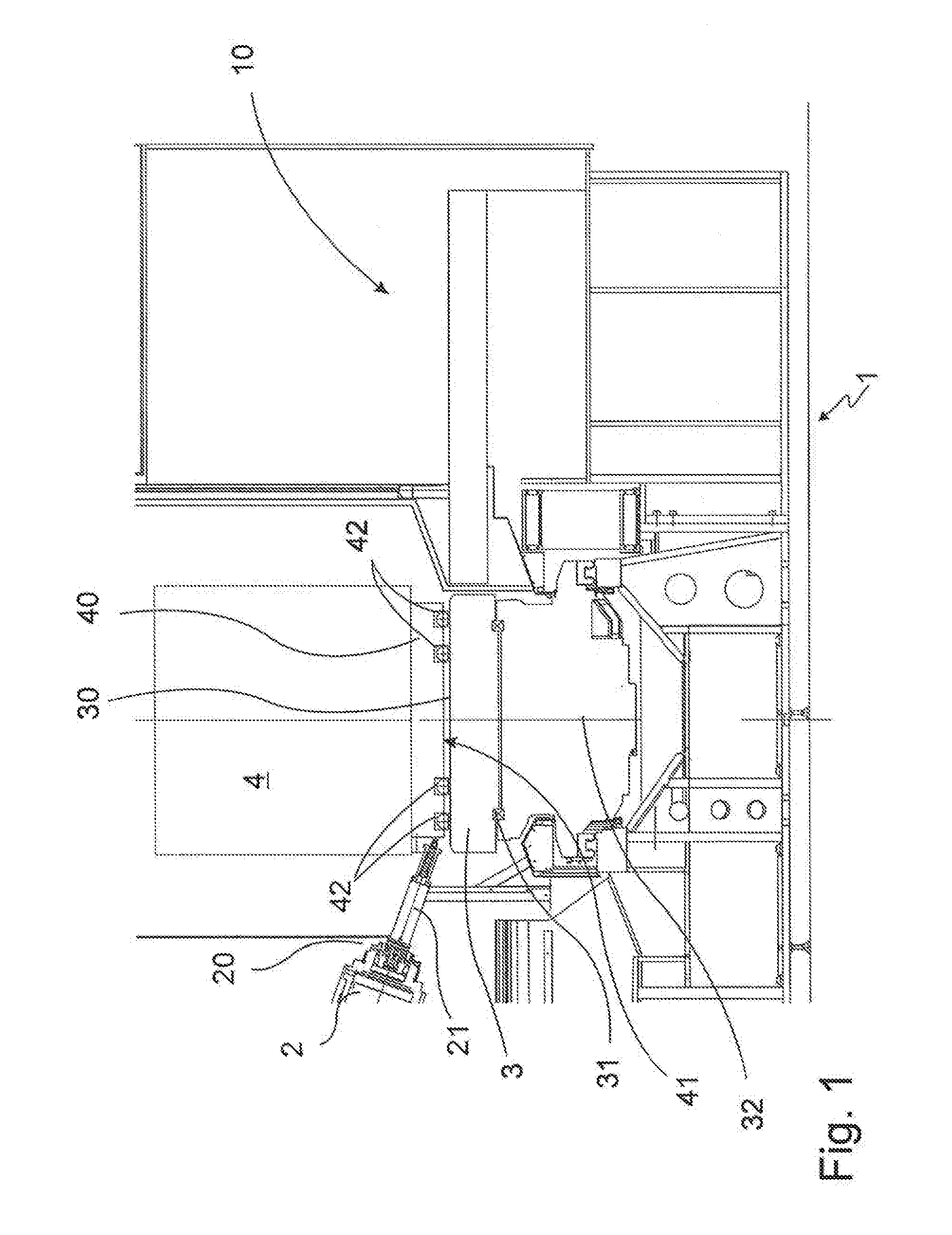
[0050]FIG. 1 shows a metal cutting machine tool 1 according to an example of the invention.

[0051]The metal cutting machine tool 1 is provided with a preparation area 10. This area is provided for introducing a work piece 4, which has to be machined by the metal cutting machine...


PUM


Abstract

The invention refers to a metal cutting machine tool, with a motor spindle, which is also used for moving a work piece between the preparation area and the work piece table. The invention also refers to a corresponding method and to a corresponding system.

Description

FIELD OF THE INVENTION[0001]The invention refers to a metal cutting machine tool. It comprises at least one motor spindle rotatably driving a respective tool. It is also provided with a work piece table, at or on which the at least one work piece is clamped, directly or indirectly by means of a pallet carrying the work piece during the machining. For transporting the work piece or the pallet carrying the work piece from a preparation area to the work piece table and back, a sliding or rolling track is provided on the work piece surface, on which the work piece or pallet is resting, or the pallet is provided on its underside with sliding rails or rollers. The motor spindle may be movably positioned by a first motor spindle linear drive at least along a first linear axis. The invention also refers to a method for swapping in a work piece on a work piece table, which can be performed, in particular, by means of above said machine tool.BACKGROUND OF THE INVENTION[0002]In known metal cut...

Claims


Application Information

Patent Timeline
IPC IPC(8): B23Q7/06B23Q7/05
CPCB23Q7/05B23Q7/06B23Q5/54B23Q7/045B23Q2230/002B23Q1/0009B23Q1/25B23Q1/44B23Q5/22B23Q7/08B23Q2705/104B23Q2701/02
Inventor GROB, H.C. BURKHART
Owner GROB WERKE & K G
Why Eureka
Try Eureka