Guiding device with measuring scale for guiding a moveable machine element of a machine

Inactive Publication Date: 2011-02-22
SIEMENS AG
View PDF29 Cites 1 Cited by
  • Summary
  • Abstract
  • Description
  • Claims
  • Application Information

AI Technical Summary

Benefits of technology

[0011]The invention is based on the object of providing a guiding device for guiding a moveable machine element of a machine, which enables exact positioning of the moveable machine element even if the machine bed oscillates.
[0013]A first advantageous refinement of the invention is characterized in that the bearing is in the form of a sliding contact bearing. Sliding contact bearings can be provided especially cost-effectively as compared to other types of bearing.
[0014]It also proves advantageous if the bearing is in the form of a rolling element bearing, since this ensures a particularly exact guidance of the measuring scale along the guiding device.
[0015]It furthermore proves advantageous if the measuring scale is connected to an anchor arranged outside the machine bed. This ensures that the measuring scale is anchored with respect to the oscillating machine bed such that it is at rest.
[0016]It furthermore proves advantageous if the anchor is a workpiece to be machined, since in that case the position of the machine element with respect to the workpiece is measured directly.
[0017]It furthermore proves advantageous if a hold-down exerts pressure on the measuring scale in the direction of the guiding device, since in that case the measuring scale is continuously in uniform contact with the bearing.

Problems solved by technology

In the process, it is frequently deformed and / or begins to oscillate.
The oscillations of the machine bed 4 frequently have such an unfavorable effect that the closed-loop control characteristics of the movement guidance of the machine element 1 are strongly compromised and not even a movement guidance of the machine element 1 in relation to the machine bed 4 that is sufficiently precise can be achieved.
In that case the oscillations of the machine bed 4 occurring during the movement guidance have a doubly disadvantageous effect.
The machine bed, however, becomes heavy, complex and expensive on account of this.
It has been shown, however, that the necessary moveable anchoring of the motor reaction surface of the linear direct drive results in significant costs and complexity.
They are therefore not used especially as a device for avoiding oscillations in machine beds of cost-effective and light-weight construction.
The measurement system, however, reacts with great sensitivity to change in the spacing between measuring scale and guiding device because, for example, the graduation marked on the measuring scale (a graduation may be provided for example in the form of lines marked on the measuring scale) can no longer be read off exactly by the reading head.
This has a very strongly negative effect on the positioning accuracy of the machine element.

Method used


Image

  • Guiding device with measuring scale for guiding a moveable machine element of a machine
  • Guiding device with measuring scale for guiding a moveable machine element of a machine
  • Guiding device with measuring scale for guiding a moveable machine element of a machine

Examples


Embodiment Construction

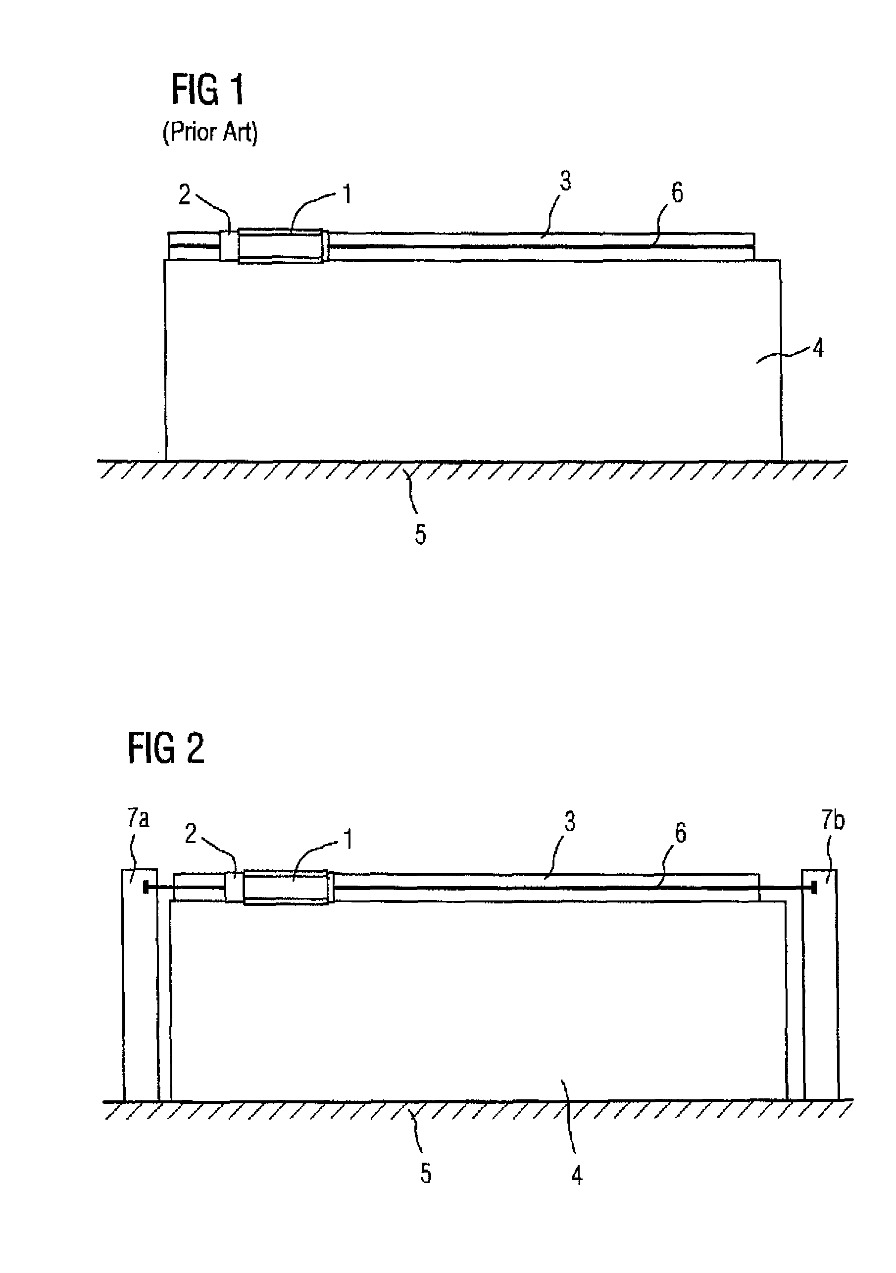
[0025]FIG. 2 shows a schematic illustration of a machine with the guiding device according to the invention. With respect to the basic design, the embodiment illustrated in FIG. 2 corresponds substantially to the embodiment described previously in FIG. 1. Identical elements are therefore provided with the same reference symbols in FIG. 2 as in FIG. 1. The essential difference with respect to the embodiment according to FIG. 1 involves the measuring scale 6 not being connected in a mechanically fixed manner to the guiding device 3, but the guiding device 3 and the measuring scale 6 being able to move in relation to one another, with at least part of the measuring scale 6 being in contact with the guiding device 3 directly or via a bearing. The bearing can be used firstly to move the guiding device 3 and the measuring scale 6 in relation to one another and, secondly, it is used to determine the spacing between reading head 2 and the measuring scale 6 exactly along the entire measuring...


PUM


Abstract

The invention relates to a guiding device (3) for guiding a displaceable machine element (1) of a machine. Said guiding device (3) in connected in a mechanically fixed manner to a machine bed (4). A material measure (6) is arranged along at least one part of the guiding device (3) in order to determine a position of the machine element (1). The guiding device (3) and the material measure (6) can be displaced in relation to each other and at least one part of the material measure (6) is in contact with the guiding device (3) either directly or via a bearing (9). The inventive guiding device (3) enables the displaceable machine elements to be positioned in a precise manner even when the machine bed (4) is vibrated. The invention also relates to a machine comprising said type of guiding device (3).

Description

BACKGROUND OF THE INVENTION[0001]The invention relates to a guiding device for guiding a moveable machine element of a machine and also to a machine having such a guiding device.[0002]In machines such as machine tools, production machines and / or robots, a moveable machine element such as a guiding carriage frequently has to be displaced in a position-regulated manner along a guiding device which may be in the form of a guiding track, for example. FIG. 1 schematically shows a commercial machine tool, where, for reasons of clarity, only those elements which are necessary to understand the invention are shown. A moveable machine element 1, which is designed in the exemplary embodiment in the commercial machine in the form of a guiding carriage, is guided by a guiding device 3, which is provided in the exemplary embodiment in the form of a guiding track. The machine element 1 is equipped with a drive, for example a linear drive, which is not shown for reasons of clarity and is used by a...

Claims


Application Information

Patent Timeline
IPC IPC(8): G01D5/347G01D5/00
CPCF16C29/00F16C29/0633F16C41/007G01D5/34707G01D5/34753
Inventor FORSTER, GERHARDHAMANN, JENSSTOIBER, DIETMAR
Owner SIEMENS AG
Why Eureka
Try Eureka