
Pneumatic clamp

A technology of pneumatic clamps and cylinders, which is applied in the direction of clamping, manufacturing tools, supports, etc., can solve the problems of insufficient machining accuracy, high repair rate, and poor usability, and achieve auxiliary locking force, control locking force, and processing high precision effect

Inactive Publication Date: 2016-01-27
KUNSHAN HONGZHIXI AUTOMATION EQUIP
View PDF9 Cites 1 Cited by
  • Summary
  • Abstract
  • Description
  • Claims
  • Application Information

AI Technical Summary

Problems solved by technology

[0002] In the processing of parts in the existing machinery manufacturing field, fixtures are usually required for clamping processing. Previously, manual clamping was generally used, which was low in efficiency, easy to skew during riveting, and high repair rate
Later, pneumatic clamps were produced, which can clamp parts and have high efficiency, but there are still shortcomings such as insufficient processing accuracy and poor usability. The clamping force of the clamps is not well grasped, which will cause some parts to be clamped too much. be damaged

Method used


Image

  • Pneumatic clamp

Examples


Embodiment Construction

[0013] The following will clearly and completely describe the technical solutions in the embodiments of the present invention with reference to the accompanying drawings in the embodiments of the present invention. Obviously, the described embodiments are only some, not all, embodiments of the present invention. Based on the embodiments of the present invention, all other embodiments obtained by persons of ordinary skill in the art without creative efforts fall within the protection scope of the present invention.

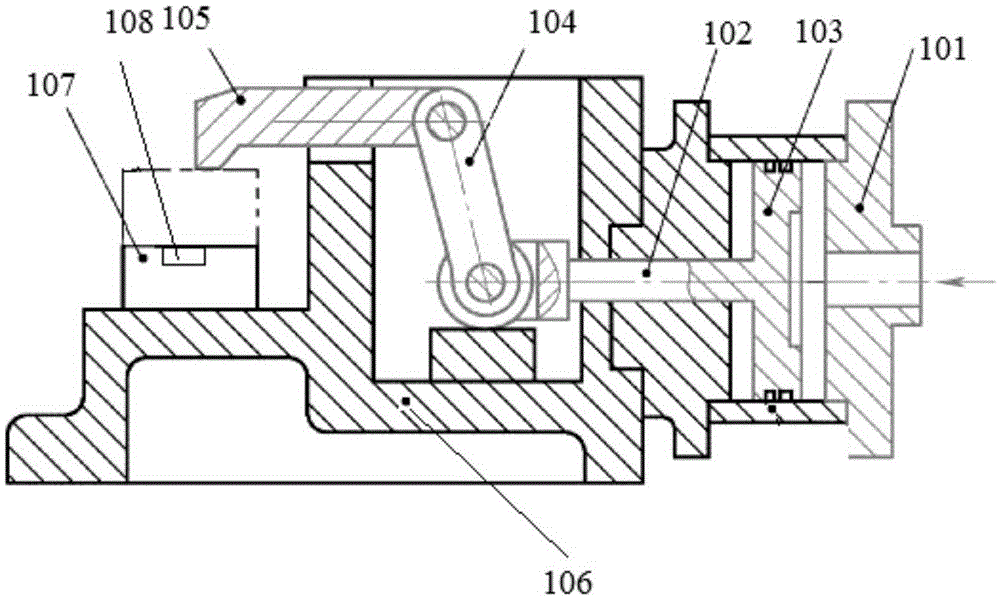
[0014] figure 1 It is a structural diagram of an embodiment of the pneumatic clamp provided by the present invention, including a cylinder 101, a connecting rod 102, a piston 103, a transmission mechanism 104, a pressing rod 105 and a bracket 106, the piston 103 is arranged in the cylinder 101, and one end of the connecting rod 102 is connected to Piston 103, the other end stretches out cylinder 101 and is connected to transmission mechanism 104, and transmission m...


PUM


Abstract

The invention discloses a pneumatic clamp. The pneumatic clamp comprises an air cylinder, a connecting rod, a piston, a transmitting mechanism, a pressing rod and a support. The piston is arranged in the air cylinder. One end of the connecting rod is connected with the piston, and the other end of the connecting rod extends out of the air cylinder and is connected to the transmitting mechanism. The transmitting mechanism is connected with the pressing rod, and the pressing rod extends out of the upper portion of the support. A cushion block is arranged on the support and located below a head of the pressing rod, and a pressure sensing alarm apparatus is arranged at the top of the cushion block. The pneumatic clamp is high in machining accuracy and usability, and the clamping force can be controlled in an assisted manner.

Description

technical field [0001] The invention relates to the technical field of mechanical manufacturing, in particular to a pneumatic clamp. Background technique [0002] In the process of parts processing in the existing machinery manufacturing field, fixtures are usually required for clamping processing. Previously, manual clamping was generally used, which was inefficient, easy to skew during riveting, and high repair rate. Later, pneumatic clamps were produced, which can clamp parts and have high efficiency, but there are still shortcomings such as insufficient processing accuracy and poor usability. The clamping force of the clamps is not well grasped, which will cause some parts to be clamped too much. be damaged. Contents of the invention [0003] The technical problem to be solved by the present invention is to provide a pneumatic clamp with high processing precision and strong usability, which can assist in controlling the clamping force. [0004] In order to solve the ...

Claims


Application Information

Patent Timeline
Patent Type & Authority Applications(China)
IPC IPC(8): B23Q3/08
CPCB23Q3/08
Inventor 孙宗仁
Owner KUNSHAN HONGZHIXI AUTOMATION EQUIP
Learn More