
Method of apparatus for cross-modal face matching using polarimetric image data

a technology of polarimetric image data and cross-modal face matching, which is applied in the direction of optical radiation measurement, instruments, sensing radiation from moving bodies, etc., can solve the problems of preventing cameras operating in the visible light spectrum from being used discreetly and effectively, unable to match an unknown thermal probe image of an individual's face to a set of known visible gallery images, and unable to achieve classification. methods with limited success

Active Publication Date: 2017-05-11
US SEC THE ARMY THE
View PDF1 Cites 57 Cited by
  • Summary
  • Abstract
  • Description
  • Claims
  • Application Information

AI Technical Summary

Benefits of technology

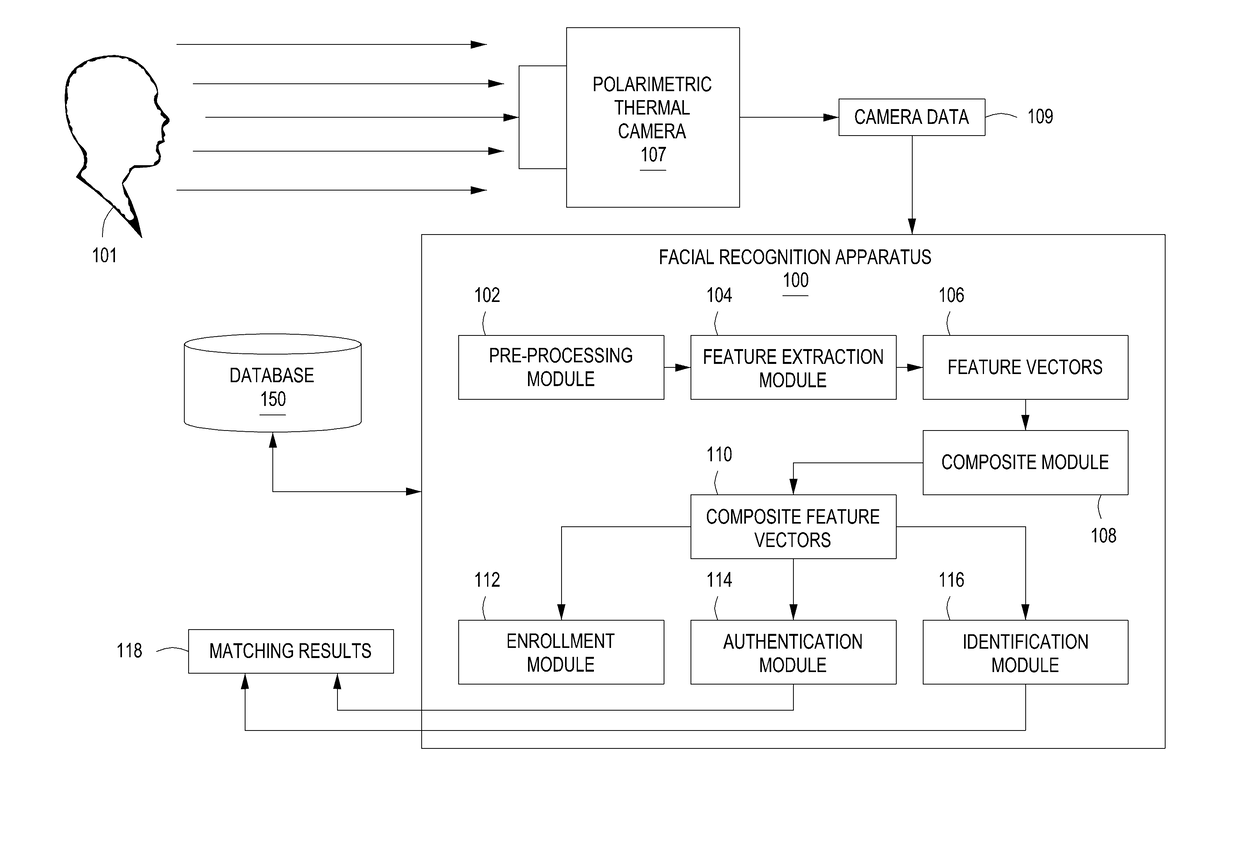
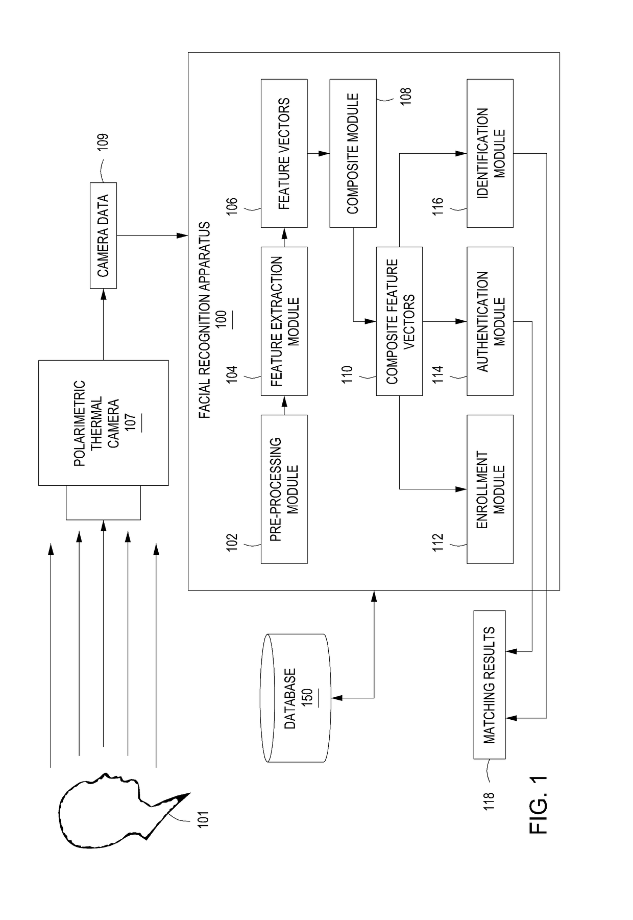
The present invention provides a method and apparatus for cross-modal face matching using polarimetric image data. This involves receiving multiple images of a face captured by a thermal imaging camera and extracting features from each image to create a composite feature vector. This vector is then cross-modally matched with other feature vectors to determine if the face matches another face. The technical effect of this invention is improved accuracy in identifying different faces through the use of polarimetric image data.

Problems solved by technology

However, for surveillance during nighttime, the lack, or absence, of illumination prevents cameras operating in the visible-light spectrum from being used discreetly and effectively.
However, as most databases and watch lists only contain facial imagery in the visible spectrum, it is difficult to match an unknown thermal probe image of an individual's face to a set of known visible gallery images.
Recently, methods consisting of preprocessing, feature extraction, and classification have been met with limited success however, since identification performance was still less than 55% for thermal-to-visible face recognition.
Thermal-to-visible face recognition algorithm performance may be fundamentally limited by the degree of correlation between the visible and thermal facial signatures, due to phenomenology and the lower spatial resolution in the thermal spectrum arising from the longer wavelength.

Method used


Image

  • Method of apparatus for cross-modal face matching using polarimetric image data
  • Method of apparatus for cross-modal face matching using polarimetric image data
  • Method of apparatus for cross-modal face matching using polarimetric image data

Examples


Embodiment Construction

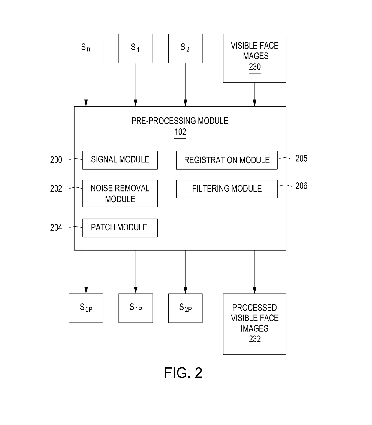
[0023]Embodiments of the present invention are directed to a method and apparatus for cross-modal face matching using polarimetric image data. Polarimetric imaging in the thermal spectrum is sensitive to changes in surface texture and geometry. The polarization-state of radiation emission (i.e., polarimetric image data) provides geometric and texture information about the surface of the imaged face, for example, prominent facial features of a person's face. For cross-modal recognition, the combination of polarimetric face features with conventional thermal face features provides a stronger correlation with the visible light feature representation and leads to better matching results than conventional thermal alone. For within-modal / spectrum matching, the polarization-state information provides fine details of the face that improve the discriminability over conventional thermal face images.

[0024]For example, in some embodiments, image data of a face is captured by a thermal camera an...


PUM


Abstract

A method and apparatus for cross-modal matching with polarimetric thermal image data is provided. According to one embodiment, the method comprises receiving a plurality of polarimetric thermal images of a face acquired by a polarimetric thermal imaging camera, extracting features of the face from each of the plurality of images to generate a plurality of feature vectors for each of the plurality of images, compositing the feature vectors for each of the plurality of images together to form composite feature vectors and cross-modally matching the composite feature vectors with other feature vectors, in order to determine whether the face matches a face represented by the other feature vectors.

Description

GOVERNMENT INTEREST[0001]Governmental Interest—The invention described herein may be manufactured, used and licensed by or for the U.S. Government. Research underlying embodiments of the present invention was sponsored by the U.S. Army Research Laboratory (ARL).FIELD[0002]Embodiments of the present invention generally relate to a method and apparatus for cross-modal face matching using polarimetric image data.BACKGROUND[0003]Automatic facial recognition has a wide range of applications in the commercial, military, and government sectors, spanning from tagging people in social networking websites to surveillance for homeland security. Face recognition research has predominantly focused on the visible spectrum, addressing challenges such as illumination variations, pose, and image resolution. However, for surveillance during nighttime, the lack, or absence, of illumination prevents cameras operating in the visible-light spectrum from being used discreetly and effectively. Thermal imag...

Claims


Application Information

Patent Timeline
IPC IPC(8): G06K9/00G01J5/02G01J5/00G06T7/00G01J5/08G06V10/30
CPCG06K9/00288G06K9/00255G06K9/00268G01J2005/0077G01J5/0825G01J5/0025G01J5/025G06T7/0085G01J5/59G06V40/166G06V40/171G06V10/30G06V40/172G06V40/168G06T7/13
Inventor SHORT, NATHANIEL J.HU, SHUOWENCHAN, ALEX L.GURTON, KRISTAN P.
Owner US SEC THE ARMY THE
Learn More