Longitudinal Support Device for Supporting a Front Engine in a Motor Vehicle

Active Publication Date: 2017-05-18
BAYERISCHE MOTOREN WERKE AG
View PDF0 Cites 5 Cited by
  • Summary
  • Abstract
  • Description
  • Claims
  • Application Information

AI Technical Summary

Benefits of technology

[0021]As a result of the fact that, in the right engine support device, the first and the second half-shell respectively each extend essentially in the longitudinal direction of the motor vehicle, i.e. the edges or margins of the engine support device are retained which, in the state of the art according to FIGS. 1 and 2 are oriented essentially continuously in a straight line and along the longitudinal axis of the vehicle, the initially mentioned problems

Problems solved by technology

An orientation of the engine support 10 that is not parallel to the main direction, i.e. the longitudinal direction, results is problematic crash behavior at low sp

Method used


Image

  • Longitudinal Support Device for Supporting a Front Engine in a Motor Vehicle
  • Longitudinal Support Device for Supporting a Front Engine in a Motor Vehicle
  • Longitudinal Support Device for Supporting a Front Engine in a Motor Vehicle

Examples


Example

DETAILED DESCRIPTION OF THE DRAWINGS

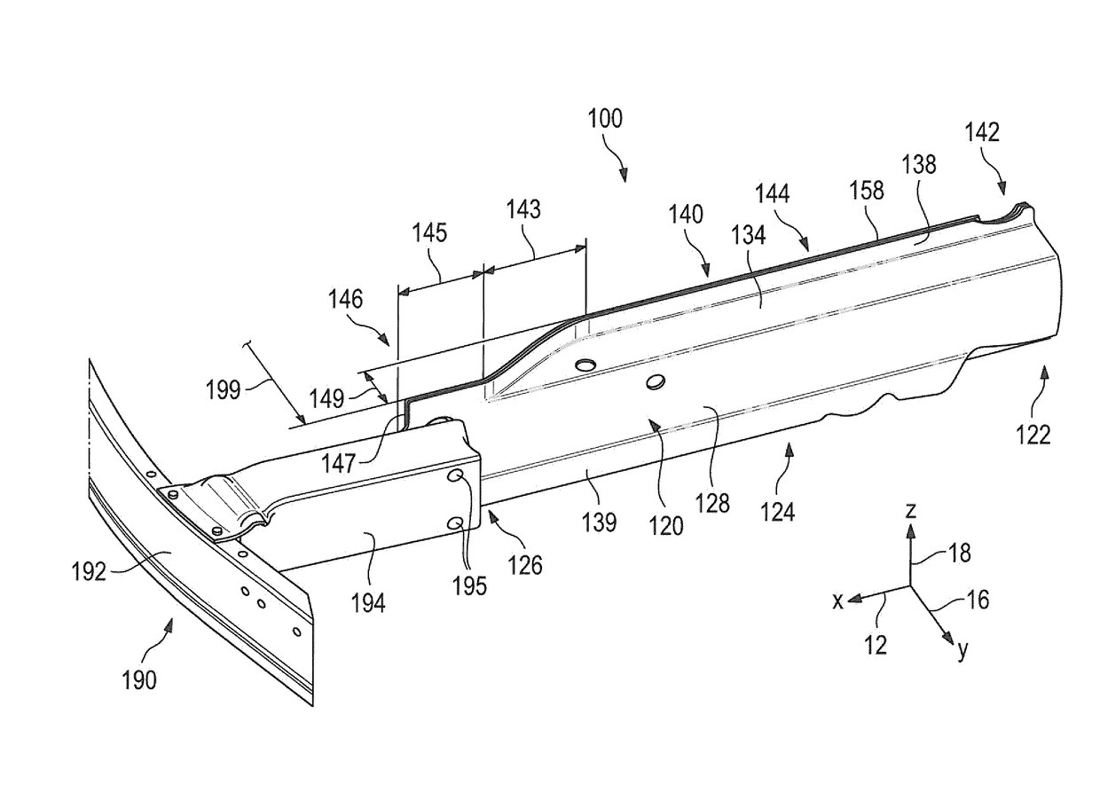
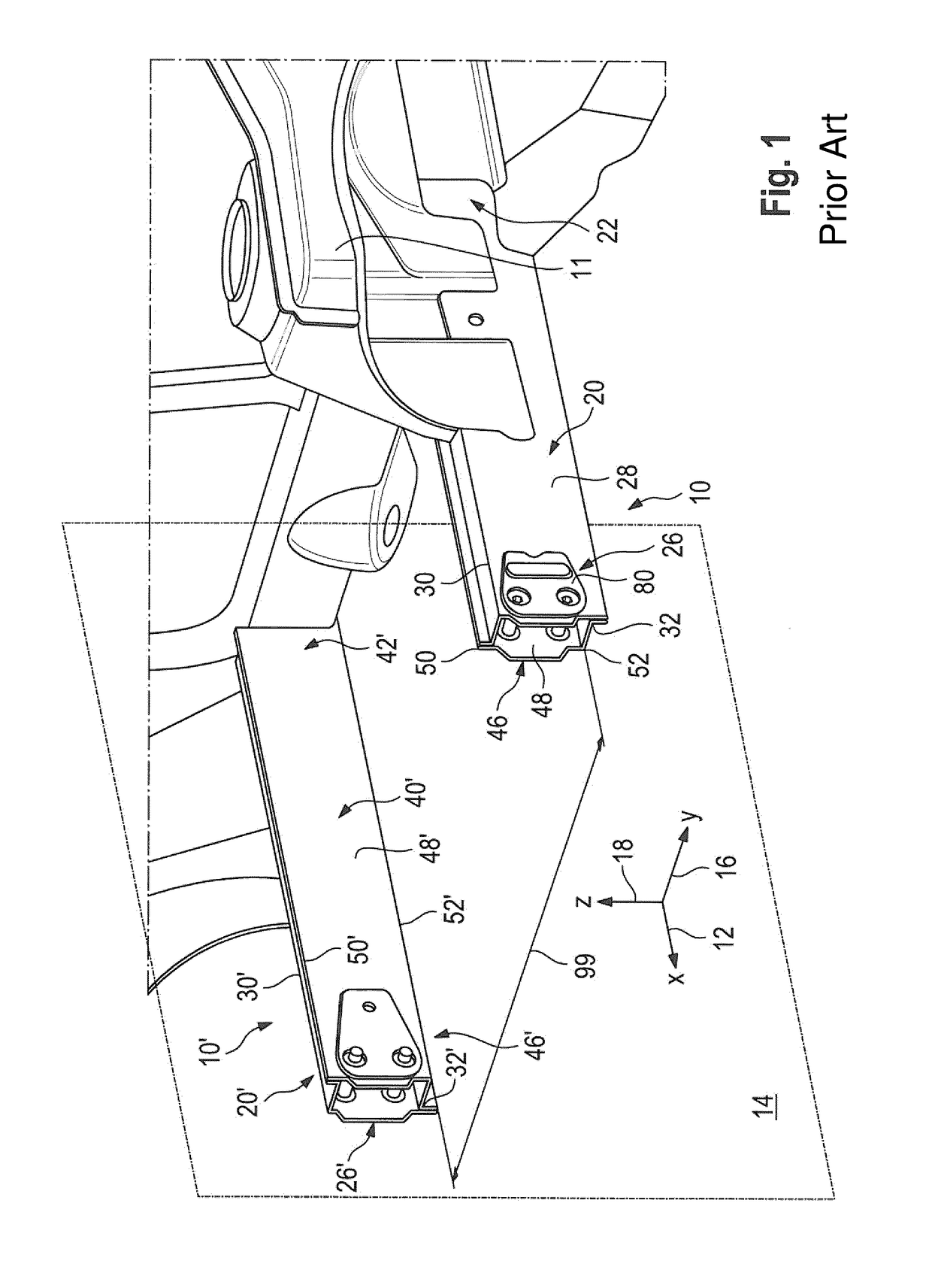
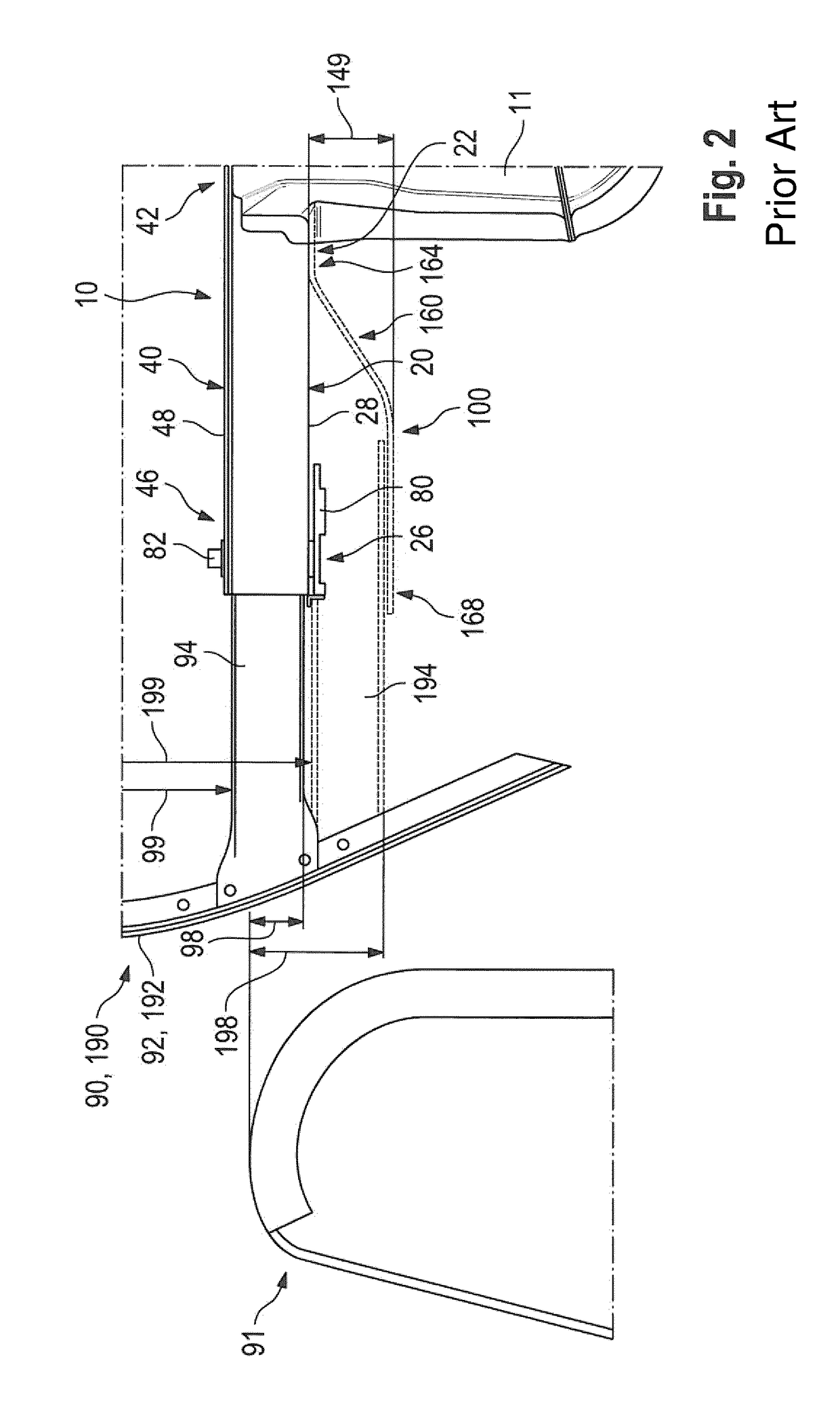
[0044]FIGS. 1 and 2 show details of a vehicle front end structure (front part) of a vehicle body of a motor vehicle having a left and a right engine support 10 and 10′ according to the state of the art. In the case of the engine supports 10 and 10′, in each case, the upper and the lower edge 30 and 32 of the first half-shell 20 and the upper and the lower edge 50 and 52 of the second half-shell 40 is constructed from its first and third (rearward) end sections 22 and 42 to its second and fourth (forward) end sections 26 and 46 essentially in a straight line, and, in the installed condition, the engine support 10 and 10′ is oriented in the direction of the longitudinal direction of the vehicle (x-direction) 12. A space having a width 99 is available between the second and fourth (forward) end sections 26 and 46 of the left and the right engine supports 10 and 10′. The space width 99 is determined by the path of the engine supports 10 and 10′, and t...


PUM


Abstract

An engine support device, which is provided for supporting an engine arranged in a front-end vehicle structure of a motor vehicle, includes a first half-shell with a first end section, a second end section opposite same and a first lateral cheek section, and a second half-shell with a third end section, a fourth end section opposite same, a middle section arranged between the third and the fourth end section and a second lateral cheek section. The first half-shell as an outer shell and the second half-shell as an inner shell can be provided in a state of the engine support device installed into a motor vehicle. The first lateral cheek section has substantially straight edges in a continuous manner from the first end section thereof to the second end section thereof. The second lateral cheek section has substantially straight edges in a continuous manner from the third end section thereof to the middle section thereof and has a first offset in the direction of the first lateral cheek section between the middle section and the fourth end section and converges on the first lateral cheek section in a first longitudinal section containing the offset by a difference in distance which corresponds to the first offset. The second lateral cheek section is arranged on the first lateral cheek section at least in the fourth and the second end sections, respectively.

Description

CROSS REFERENCE TO RELATED APPLICATIONS[0001]This application is a continuation of PCT International Application No. PCT / EP2015 / 067460, filed Jul. 30, 2015, which claims priority under 35 U.S.C. §119 from German Patent Application No. 10 2014 214 913.4, filed Jul. 30, 2014, the entire disclosures of which are herein expressly incorporated by reference.BACKGROUND AND SUMMARY OF THE INVENTION[0002]The present invention relates to a longitudinal or engine support device for supporting an engine, particularly a front engine, which device is arranged in a front end vehicle structure of a motor vehicle.[0003]In known vehicle body concepts in the field of motor vehicle construction, longitudinal supports or engine supports in a sheet metal shell or profile construction are known, which are made of steel and / or aluminum. The known longitudinal or engine supports have an essentially constant, for example, rectangular cross-sectional profile along their course from a rearward to a forward end...

Claims


Application Information

Patent Timeline
IPC IPC(8): B62D21/15B62D25/08B60R19/24B62D21/11
CPCB62D21/152B60R19/24B62D25/082B62D21/11
Inventor BOKELOH, JAN
Owner BAYERISCHE MOTOREN WERKE AG
Why Eureka
Try Eureka