Eureka AIR delivers breakthrough ideas for toughest innovation challenges, trusted by R&D personnel around the world.

Protective cover

a protective cover and protective technology, applied in the field of protective covers, can solve the problems of affecting and removing the layer or particles, etc., and achieve the effect of not impairing the effectiveness of wound treatmen

Active Publication Date: 2020-02-25
MEDAXIS
View PDF40 Cites 3 Cited by
  • Summary
  • Abstract
  • Description
  • Claims
  • Application Information

AI Technical Summary

Benefits of technology

The object of the present invention is therefore to provide a protective cover which in a simple manner provides reliable protection against contamination without impairing the effectiveness of wound treatment.
The stiffening element can be disposed between an inner and an outer layer of the web of material of the funnel-shaped hollow body, whereby reliable and stationary positioning of the stiffening element protected against external influences is obtained.

Problems solved by technology

However, the high pressure of the fluid jet does not only lead to the removal of the layer or of the particles from the wound, but inevitably also to an aerosol (fluid mist) around the wound composed of droplets of body fluid and irrigation fluid floating in the air.
In the event that no protective measures are taken, such aerosols can freely escape into the environment and thus pose a significant hazard to patients and / or the respective health care professional.
The high hazard potential of such aerosols is due to the fact that wounds almost always are colonized by pathogens (such as bacteria, viruses or fungi), whereby also the aerosols being produced during their treatment represent a potentially infectious medium because they are laden with pathogens.
Consequently, dangerous cross-infection could in the absence of additional protection measures occur between the patients and the individuals present in the treatment room or the individuals later entering the treatment room or the individuals later using the treatment equipment.
In addition, free distribution of the aerosol during wound treatment would lead to contamination in the treatment room, in particular of the treatment table and the surrounding floor surfaces.
This in turn results in an increased risk of slipping and thereby the risk of injury to individuals in the treatment room.
A further problem is the obstruction of the view onto the treatment area when the freely spreading aerosol e.g. collects on the protective glasses of the attending person.
Such protective foils, however, offer only inadequate protection for the health care professionals and patients from body and irrigation fluids laden with bacteria, viruses, fungi, parasites and / or other pathogens spraying back.
Firstly, such pathogens can naturally enter the environment through the two hand openings.
Secondly, it is disadvantageous that the gloved hand still needs to reach into the treatment chamber located under the protective foil and contaminated with aerosol.
Also disadvantageous is that the visibility and the splash protection effect are inversely proportional to each other.
Though protective foils with extensions designed as gloves for an attending person to slip into are known, such integrated solutions are disadvantageous, however, in that forcing the hands into or out from then glove extensions proves to be very difficult.
In addition, the drawback remains that the attending person must reach into the aerosol-contaminated treatment chamber.
A drawback of such devices is that the motion performed during wound treatment by the suction / irrigation tip must also be carried out by the splash shield that bears snugly on the patient's skin.
This motion can by the patient be perceived as being painful.
Dangerous, highly contagious fluid droplets can thereby escape into the environment despite the splash shield.
Such systems, however, are very complex in design since not only fluid supply but also additional extraction (possibly with recirculation of the irrigation fluid) must be present.

Method used


Image

  • Protective cover
  • Protective cover
  • Protective cover

Examples


Embodiment Construction

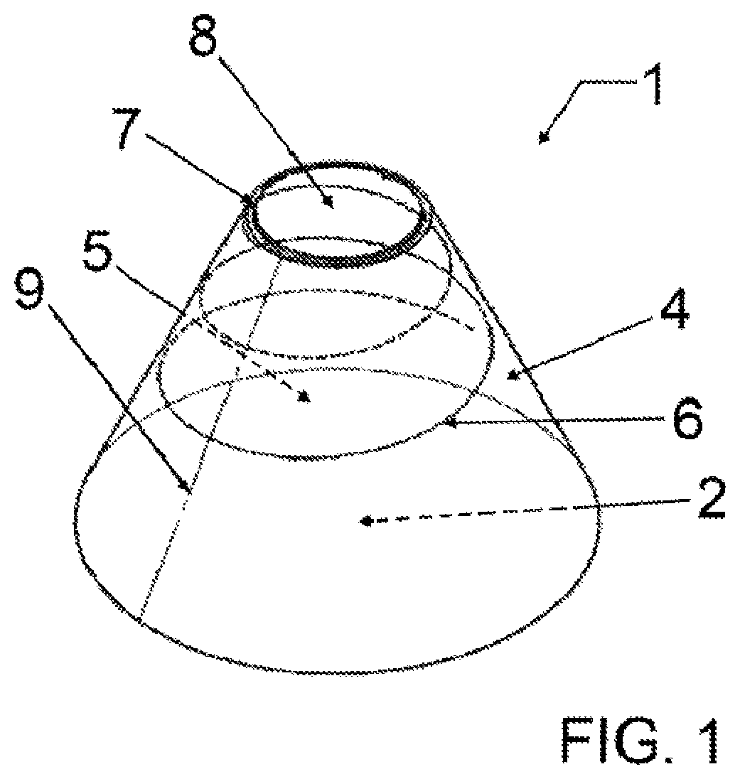
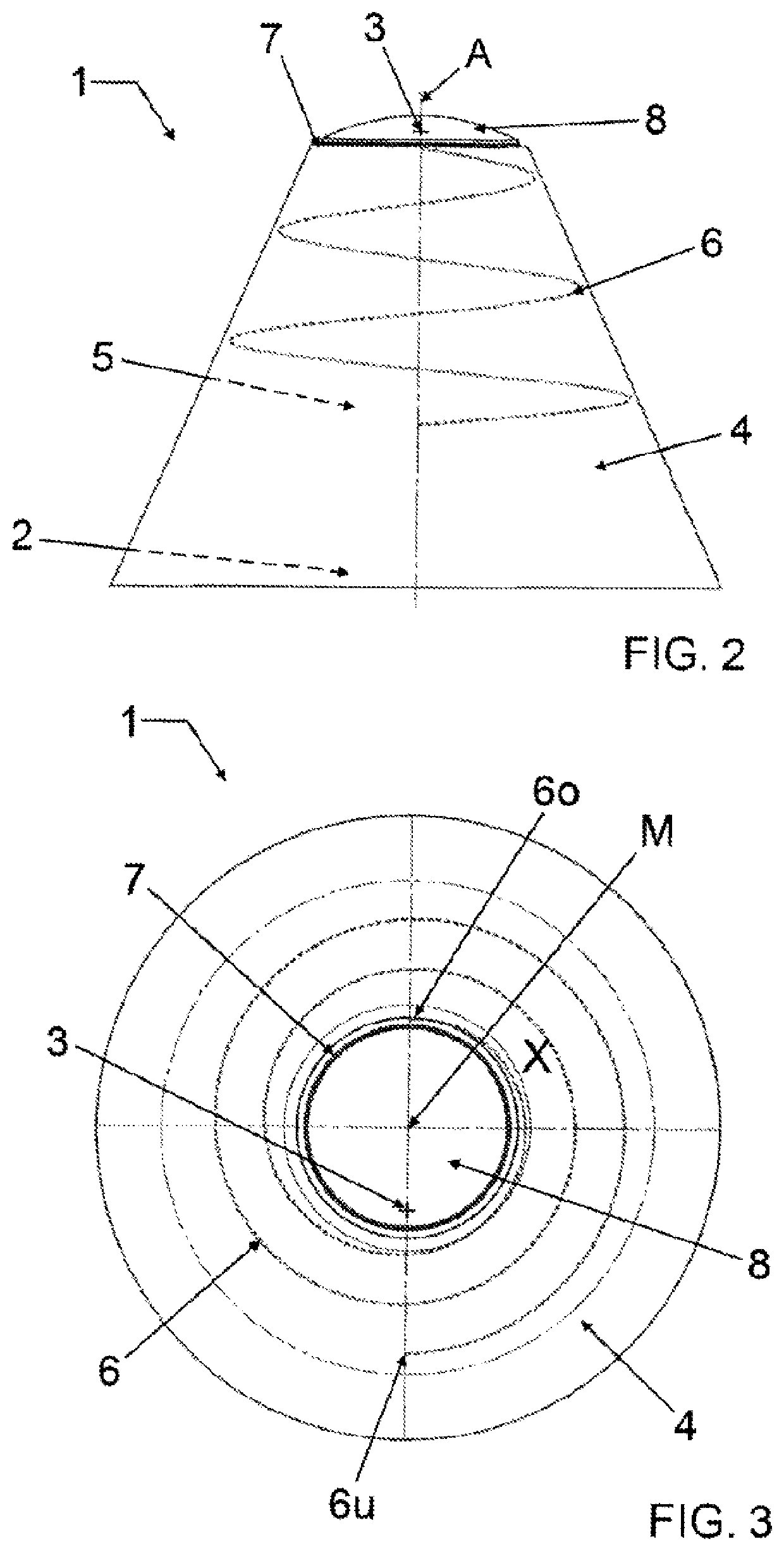
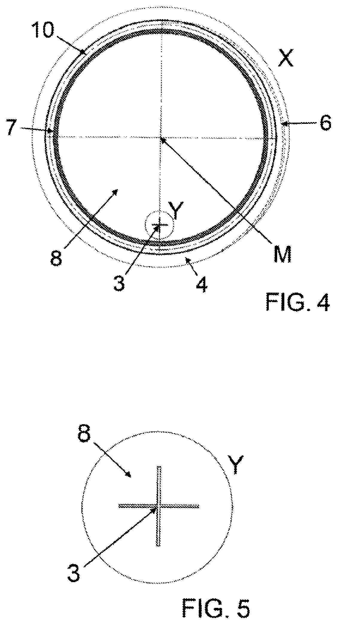
Protective cover 1 according to the invention illustrated in FIGS. 1, 2 and 3 respectively in an overall view in its non-deformed initial state has a shape resembling a jellyfish. The core component of protective cover 1 is there formed by an axially symmetric funnel-shaped hollow body 4 which along its longitudinal axis A comprises two openings 2, 7 which are in turn arranged axially and diametrically opposite to one another, where these openings 2, 7 are of different size.

Larger opening 2, in FIGS. 1 and 2 respectively facing downwardly, is in the later use placed on a body part of a patient, generally a limb, where the edges of opening 2 define a treatment area in which a wound to be treated with an irrigation fluid jet or other skin disorders of the patient (e.g. an ulcer) is located.

Hollow body 4 encloses a frustoconical interior which in later use acts as a treatment chamber 5 into which the head end (not shown) of a handpiece is introduced, from which in turn an irrigation fl...


PUM


Abstract

A protective cover for the protection against contamination from body and / or irrigation fluid during treatment of wounds / ulcers includes a first opening to be placed on a patient and a second opening for inserting a handpiece. The protective cover includes a fluid-tight and flexible hollow body that defines a treatment chamber having a shape that adapts to motion of a handpiece. The hollow body may include a stiffening element for keeping the first opening in an open state during treatment. Additionally, a device for the irrigation of wounds or ulcers, such as for debriding dead body tissue by way of a micro water jet, may include a hand-operated lance with a nozzle for producing an irrigation fluid jet, such as a micro water jet. The lance may be inserted through the second opening of the protective cover so that the nozzle is located within the treatment chamber of the protective cover.

Description

CROSS REFERENCE TO RELATED APPLICATIONSThis application claims the benefit of priority to European patent application No. 15182057.8, filed Aug. 21, 2015, which is incorporated herein by reference in its entirety as though fully set forth herein.TECHNICAL FIELDThe present invention relates to a protective cover for the protection against contamination from body and / or irrigation fluid during the treatment of wounds or ulcers. It further relates to a device equipped with such a protective cover for irrigating wounds or ulcers.BACKGROUNDIrrigation is a commonly used method for cleaning open, contaminated and chronic wounds. During irrigation, sterile irrigation fluids act upon wounds to remove lifeless tissue, bacterial inoculum, blood clots, loose dirt and foreign bodies in the vicinity and in the depths of the wound. The critical parameters of any wound irrigation method are the application of an adapted volume of sterile irrigation fluid to the wound and the use of sufficient press...

Claims


Application Information

Patent Timeline
Patent Type & Authority Patents(United States)
IPC IPC(8): A61F15/00A61B90/40A61B46/27A61M3/02A61F13/00A61B46/23A61B90/00A61B17/3203A61M1/00
CPCA61B46/23A61M3/0279A61B90/05A61B46/27A61F15/008A61B90/40A61F2013/00182A61M1/0058A61F2013/00165A61F2013/00306A61B17/3203A61F13/00068A61F2013/00297A61M3/02
Inventor MOSER, BEATZWEIFEL, ADRIANSELEK, OEZKANWIDMER, BEATGOOD, ROMAN
Owner MEDAXIS
Why Eureka
Eureka Blog
Learn More