Exhaust manifold for internal combustion engine

a technology for exhaust manifolds and internal combustion engines, which is applied in the direction of engines/engines, machines/engines, mechanical apparatus, etc., can solve the problems of reduced fuel consumption in a rated horsepower point, long load application time(load making time), and reduced acceleration performance, so as to achieve the effect of reducing load application time and achieving the same effect or advantag

Inactive Publication Date: 2007-04-12
YANMAR CO LTD
View PDF6 Cites 1 Cited by
  • Summary
  • Abstract
  • Description
  • Claims
  • Application Information

AI Technical Summary

Benefits of technology

[0010] According to the invention of claim 1, the load application time (build up time) can be reduced without worsening the fuel consumption. According to the invention of claim 2, 3 and 4, the same effectiveness or advantage as invention of claim 1 can be done so.

Problems solved by technology

According to the latter, its fuel consumption in a rated horsepower point is reduced, however, its acceleration performance is inferior as compared with the former.
In this FIG. 1, it turns out that the load application time(load making time) becomes long although the fuel consumption will become good when the diameter of the main tube is greatly set up, on the contrary, the load application time will become short although fuel consumption gets worse when the diameter of the main tube is set up small.

Method used


Image

  • Exhaust manifold for internal combustion engine
  • Exhaust manifold for internal combustion engine
  • Exhaust manifold for internal combustion engine

Examples


Embodiment Construction

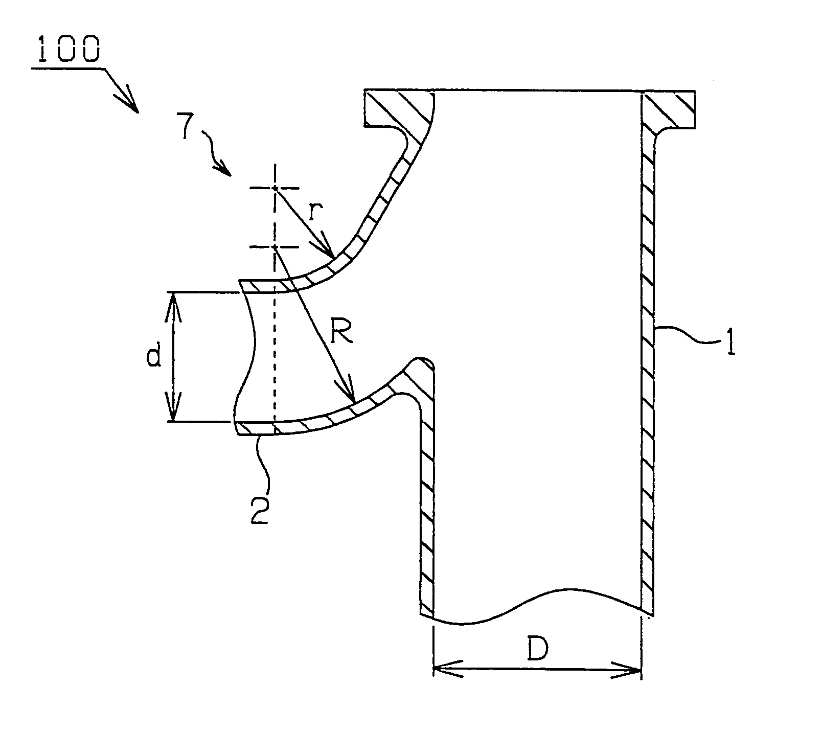
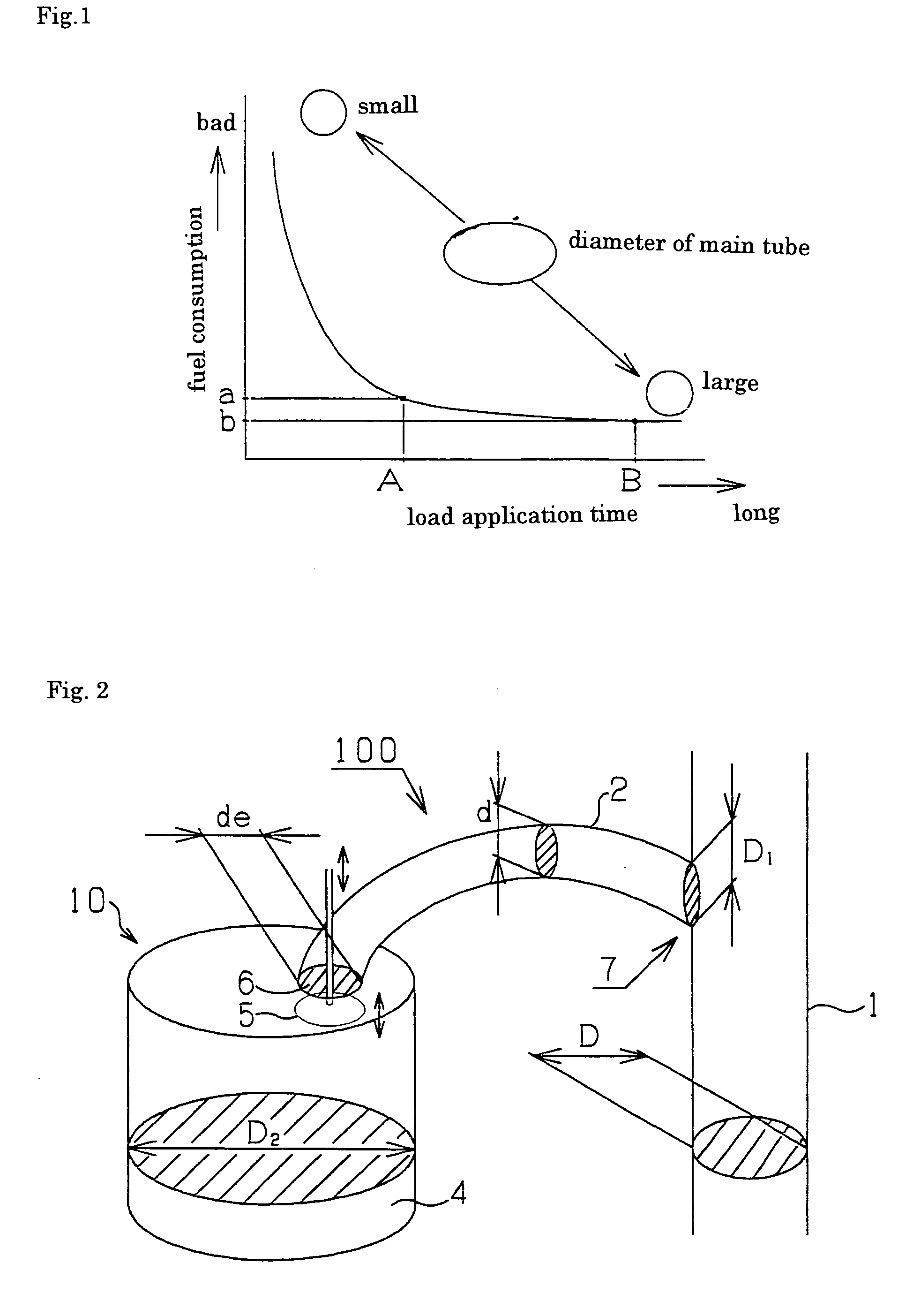
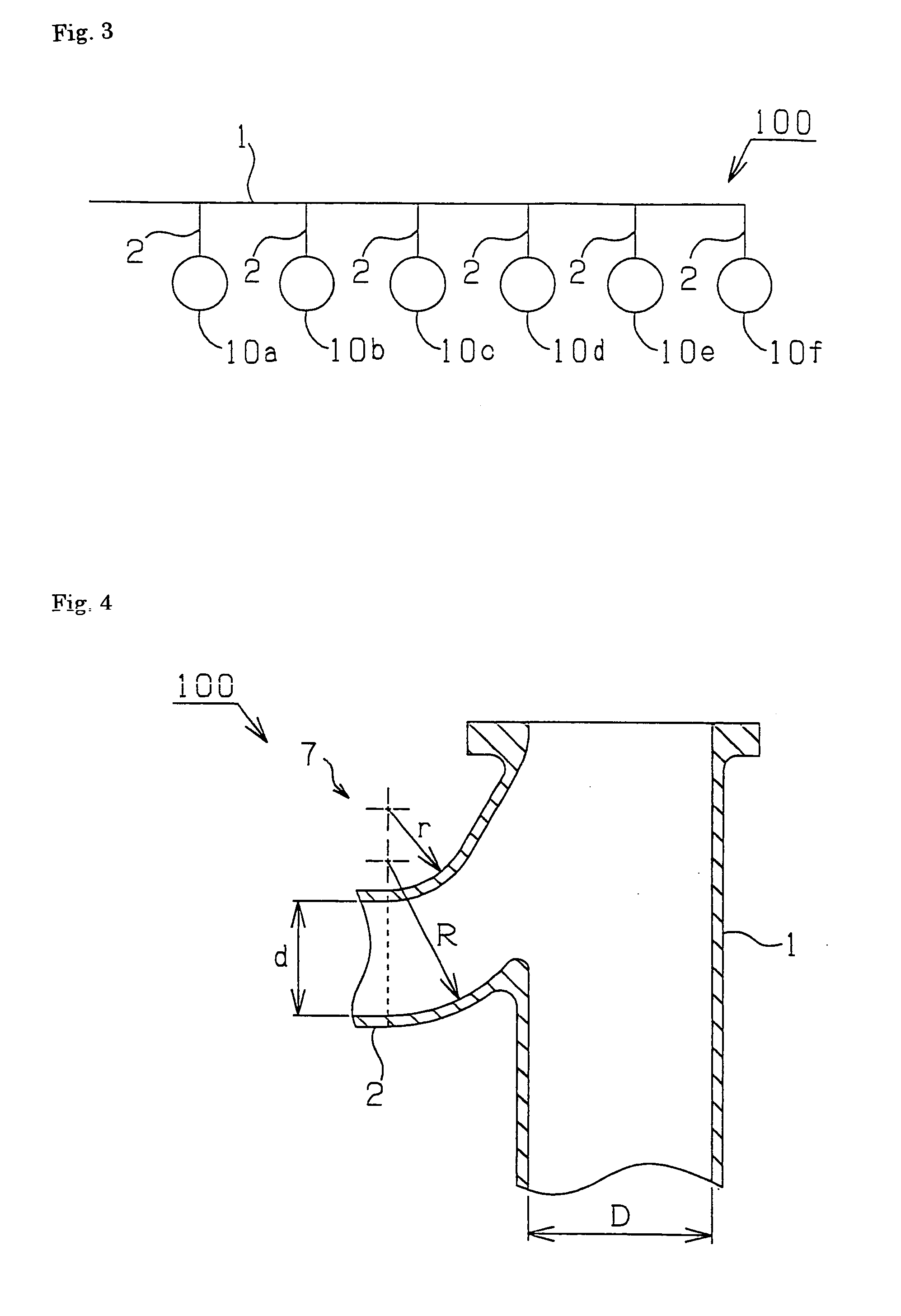
[0034]FIG. 2 is a schematic appearance view of the exhaust manifold of the internal combustion engine according to the present invention. As for the exhaust manifold 100, one end of a branch tube 2 is connected to a side wall of a main tube 1. Another end of the branch tube 2 is connected to an exhaust port 6 of a cylinder 10. An exhaust valve 5 is arranged in the exhaust port 6 so as to be movable in the direction of the arrow. The exhaust port 6 can be opened and closed with the exhaust valve 5. As shown in FIG. 3, a structure of the exhaust manifold 100 is simplified by connecting each cylinder 10a-10f to a main tube 1 via each branch tube 2.

[0035] As shown in FIG. 2, at first, the dimension of the suitable diameter de of an exhaust valve sheet corresponding to the diameter D2 of a boa, which is equivalent to a diameter of a piston 4, is determined. The diameter d of the branch tube 2 is set up so that its dimension may not change rapidly from the diameter de of the exhaust valv...


PUM


Abstract

The present invention relates to an exhaust manifold for a supercharger-equipped internal combustion engine having multiple cylinders capable of preventing an increase in the fuel consumption and of reducing load application time. The engine satisfies at least one of the following expressions, where D is the diameter of a main tube of the exhaust manifold, d is the diameter of a branch tube, D1 is the diameter of a passage of a connection connecting the branch tube to the main tube, R is the radius in the outer peripheral side of the connection smoothly connecting the branch tube to the main tube of the exhaust manifold, and r is the radius in the inner circumference side. 1.2≦(D/d)2 ≦2.5, 0.8≦(d/de)2≦1.2, 0.7≦(D/D1)2≦1.4, 1.7≦R/r≦2.1.

Description

TECHNICAL FIELD [0001] The present invention relates to an exhaust manifold for a supercharger-equipped internal combustion engine having multiple cylinders. BACKGROUND ART [0002] There are two sorts of turbocharging systems in an exhaust manifold of an internal combustion engine with a supercharger. One is a pulse turbocharging system and another is a constant-pressure turbocharging system. In the former, it is set up so as to make an exhaust pulse large or enhance in an inlet-port section of a turbine, and the supercharger is driven by the enhanced exhaust pulse. According to the former, its acceleration performance is improved, however, its fuel consumption at a rated horsepower point is increased. In the latter, it is set up so as to change the exhaust pulse into static pressure for using a part with high supercharger effectiveness. According to the latter, its fuel consumption in a rated horsepower point is reduced, however, its acceleration performance is inferior as compared ...

Claims


Application Information

Patent Timeline
Patent Type & Authority Applications(United States)
IPC IPC(8): F01N5/02F01N7/00F01N13/10F02F1/42F02N7/10
CPCF01N13/10F02F1/4264F01N13/18
Inventor OMOTE, HIROSHIHAMAOKA, SHUNJITSUJIMOTO, KEIICHI
Owner YANMAR CO LTD
Why Eureka
Try Eureka