Printing device, printing device control program, printing device control method, print data generation device, print data generation program, and print data generation method

a printing device and control program technology, applied in the direction of instruments, visual presentations, computing, etc., can solve the problems of deteriorating printing quality, too large or too small ink quantity in comparison with ideal quantity, and printing takes a considerable long time in comparison with a printing device adopting another method

Inactive Publication Date: 2006-08-03
SEIKO EPSON CORP
View PDF11 Cites 10 Cited by
  • Summary
  • Abstract
  • Description
  • Claims
  • Application Information

AI Technical Summary

Benefits of technology

[0142] The same function and advantage as the print data generation device of the thirty-first aspect can be thus achieved.

Problems solved by technology

Hence, it has a drawback that printing takes a considerably long time in comparison with a printing device adopting another method, such as a laser printer using electrophotographic technology such as in a copying machine.
This configuration, however, may possibly give rise to a so-called flight deviation (or flight bend) phenomenon, which is an event that the ink ejecting direction of a part of the nozzles is inclined due to a manufacturing error or the landing position of a dot formed by a given nozzle is displaced from the ideal position because this nozzle is disposed at a position displaced from the ideal position.
In addition, the characteristic varies from nozzle to nozzle, and for a nozzle having a considerable variance, a quantity of ink becomes too large or too small in comparison with an ideal quantity.
Defective printing referred to as the so-called banding (streak) phenomenon thus occurs in a portion printed by such failing nozzles, which possibly deteriorates the printing quality.
In other words, once the flight deviation phenomenon occurs, a distance between dots ejected from adjacent nozzles becomes uneven.
However, it is difficult to provide a print head that is 100% free from the banding phenomenon because of the limits to hardware improvement due to manufacturing costs and current technical abilities.
However, the first technique in the related art for suppressing the banding phenomenon and variances using another color has a problem that the hue changes in a portion where this technique is applied.
This technique is therefore unsuitable for printing that requires a high image quality and a high quality, such as printing of a color picture image.
In addition, when the method of avoiding the white streak phenomenon by distributing the information about the non-ejecting nozzle to nozzles on the right and left is adopted as a countermeasure against the flight deviation phenomenon, it is indeed possible to reduce a white streak; however, there is a problem that banding still occurs in a dense portion.
However, this technique cannot be used when halftone printed matter is produced.
This technique therefore has the same problem as the first technique in the related art.
The third technique in the related art has difficulty solving a problem that the dot formation content has discrepancies, because complicated processing is required to enable appropriate feedback for solving such a problem.
The fourth technique in the related art has a problem that in a case where dots of different sizes are formed using nozzles in the neighborhood in the downstream processing after binarization, when the dots have a γ characteristic, there is a risk that the area grayscale is lost in the portion where this technique is applied.
As has been described, the banding phenomenon includes a printing failure in which a white streak and a dark steak occur simultaneously in the printing result due to the so-called flight deviation phenomenon caused by a nozzle whose dot forming position is displaced from the ideal forming position, a printing failure in which a white streak or a dark streak occurs in the printing result due to an inadequate quantity of ejected ink caused by a non-ejecting nozzle, and a printing failure in which a white streak or a dark streak occurs in the printing result due to the γ characteristic of a dot formed by the nozzle.
A white streak may occur because of a nozzle having an insufficient quantity of ink, whereas a dark streak may occur because of a nozzle having an excessive quantity of ink.
An ink ejection failure means a state where a nozzle is incapable of ejecting ink in an ideal manner, for example, in a case where the nozzle is totally incapable of ejecting ink, a quantity of ejected ink is insufficient, a quantity of ejected ink is excessive, or the nozzle is not able to eject ink at the ideal position.

Method used


Image

  • Printing device, printing device control program, printing device control method, print data generation device, print data generation program, and print data generation method
  • Printing device, printing device control program, printing device control method, print data generation device, print data generation program, and print data generation method
  • Printing device, printing device control program, printing device control method, print data generation device, print data generation program, and print data generation method

Examples


first embodiment

[0168] Hereinafter, a first embodiment of the invention will be described with reference to the accompanying drawings. FIG. 1 through FIG. 14 are views showing the first embodiment of a printing device, a printing device control program, a printing device control method, a print data generation device, a print data generation program, and a print data generation method of the invention.

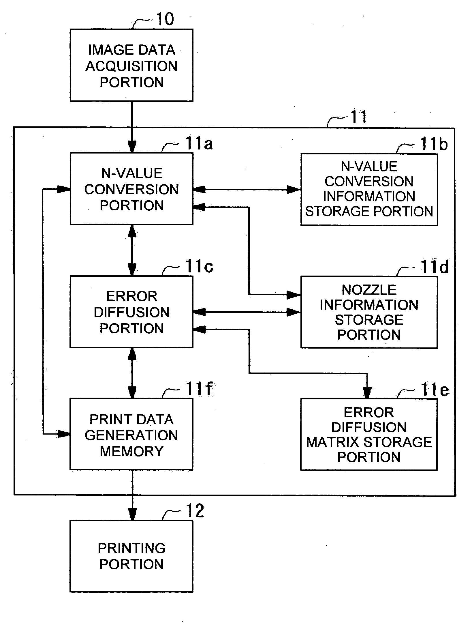
[0169] Firstly, the configuration of a printing device 100 of the invention will be described with reference to FIG. 1. FIG. 1 is a block diagram showing the configuration of the printing device 100 of the invention.

[0170] The printing device 100 is a line-head printing device. As is shown in FIG. 1, it comprises an image data acquisition portion 10 that acquires M-value (M≧3) image data from an external device or a storage medium, a print data generation portion 11 that generates print data used for a printing portion 12 described below to print an image of the image data on a print medium (for exa...

second embodiment

[0246] A second embodiment of the invention will now be described with reference to the accompanying drawings. FIG. 15 is a view showing the second embodiment of the printing device, the printing device control program, the printing device control method, the print data generation device, the print data generation program, and the print data generation method of the invention.

[0247] The configurations of the printing device and the computer system of the second embodiment are the same as their counterparts of the first embodiment shown in FIG. 1 and FIG. 2, respectively. In the second embodiment, the print data generation processing performed in Step S106 in FIG. 5 of the first embodiment is replaced with the one in FIG. 15.

[0248] The generation principle underlying the print data generation processing of FIG. 15 is the same as the one in the first embodiment except that the selected pixel data corresponding to a nozzle having an ink ejection failure is not converted to an N value...


PUM


Abstract

A device including: an acquirer acquiring image data having an M-value (M≧3) pixel value; a memory storing nozzle information; another memory storing error diffusion matrices having different diffusion ratios of an error; a selector selecting specific pixel data in the image data; an N-value converter converting the M-value to an N value (M>N≧2); a diffuser diffusing the error to pixel data not subjected to the conversion in the image data according to the error diffusion matrix by using a difference between a selected pixel data value before and after conversion as the error; a generator generating print data defining nozzle dot information corresponding to the image data after the conversion; and a printer. The diffuser selects a specific error diffusion matrix for each selected pixel data according to the nozzle information, and diffuses the error to the pixel data not subjected to the conversion.

Description

RELATED APPLICATIONS [0001] This application claims priority to Japanese Patent Application Nos. 2005-020834 filed Jan. 28, 2005 and 2005-279404 filed Sep. 27, 2005 which are hereby expressly incorporated by reference herein in their entirety. BACKGROUND [0002] 1. Technical Field [0003] The present invention relates to a printing device used in a facsimile machine, a copying machine, and office automation equipment, a printing device control program, and a printing device control method, and more particularly, to a so-called ink-jet printing device configured to draw specific characters and images by ejecting fine particles of liquid inks of several colors onto a print sheet (recording member), a printing device control program, a printing device control method, a print data generation device, a print data generation program, and a print data generation method. [0004] 2. Related Art [0005] Hereinafter, a printing device, in particular, a printer adopting the ink jet method (hereinaf...

Claims


Application Information

Patent Timeline
Patent Type & Authority Applications(United States)
IPC IPC(8): H04N1/40
CPCH04N1/4052
Inventor TAKAHASHI, TORU
Owner SEIKO EPSON CORP
Why Eureka
Try Eureka