Conical scanning process for spacecraft sun pointing

a scanning process and spacecraft technology, applied in the field of spacecraft sun search and pointing, can solve the problem that the process requires the use of relatively complicated sensors

Active Publication Date: 2017-05-25
CHARLES STARK DRAPER LABORATORY
View PDF0 Cites 7 Cited by
  • Summary
  • Abstract
  • Description
  • Claims
  • Application Information

AI Technical Summary

Problems solved by technology

These processes require the use of relatively complicated sensors.

Method used


Image

  • Conical scanning process for spacecraft sun pointing
  • Conical scanning process for spacecraft sun pointing
  • Conical scanning process for spacecraft sun pointing

Examples


Embodiment Construction

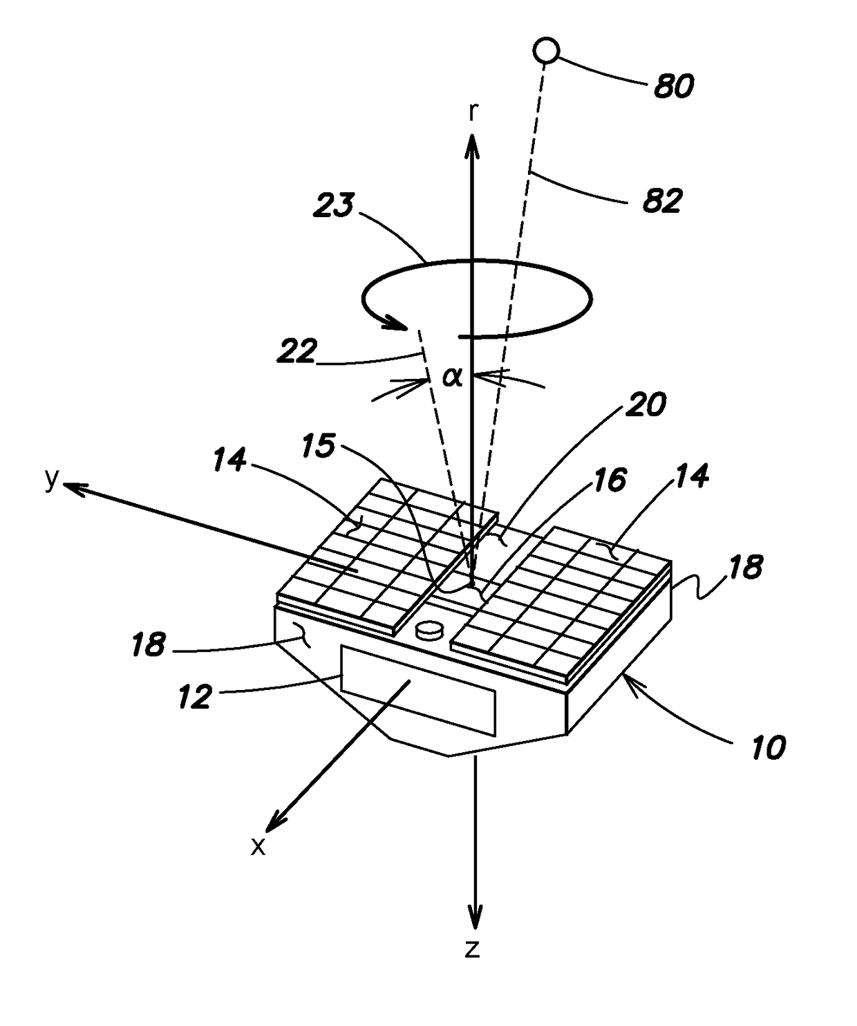
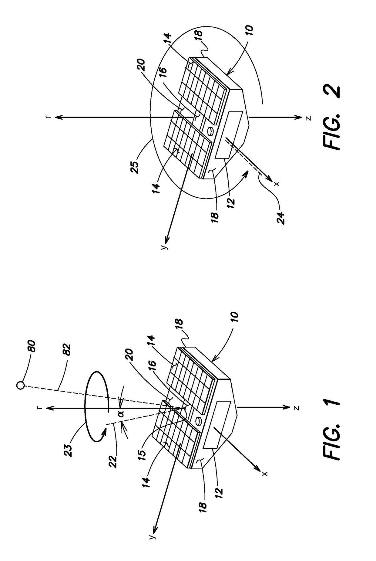
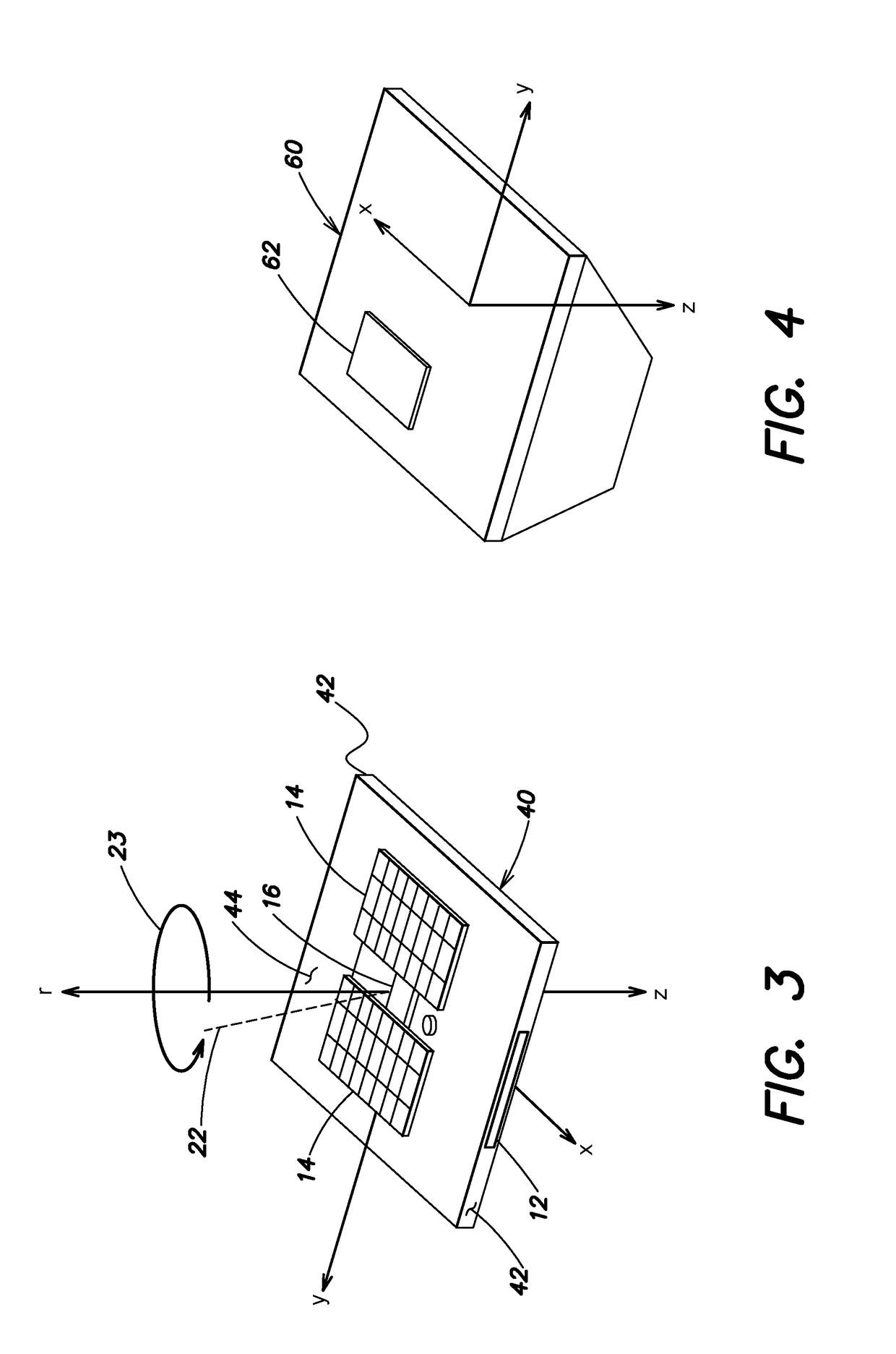
[0035]Orienting a spacecraft towards the Sun has applications both to attitude acquisition following deployment of the spacecraft from a launch vehicle and to attaining a safe state of the spacecraft following an anomaly in orbit. Aspects and embodiments disclosed herein provide systems and methods for a spacecraft to locate and orient itself towards the Sun, or another energy or signal source, with source measurements provided only by incidence-angle sensors and / or presence sensors such as photocells. Such a sensor suite may not provide enough information to determine the instantaneous direction toward the source. However, certain embodiments include a process that commands a dynamically stable spacecraft maneuver which both simplifies the control architecture and allows the spacecraft processor(s) to construct an estimate of the source direction by tracking sensor measurements in a buffer. The process then drives the spacecraft to orient its sensors toward the source. For example,...


PUM


Abstract

A conical scanning method and system is provided for orienting a spacecraft with respect to a source. The system includes a spacecraft and an incidence angle sensor secured to the spacecraft to sense a signal from a source. The incidence angle sensor has a boresight that is canted with respect to the principal axis. A processor communicates with actuators on the spacecraft to adjust an attitude of the spacecraft based on information received from the incidence angle sensor and to thereby align a principal axis of the spacecraft with a direction from the spacecraft to the source. The method and system can also rely on information received from source presence sensors. The source may be the Sun, or a non-solar signal source.

Description

CROSS REFERENCE TO RELATED APPLICATION[0001]This application claims priority under 35 U.S.C. §119(e) to co-pending U.S. Provisional Application Ser. No. 62 / 259,329 titled “Conical Scanning Algorithm for Spacecraft Sun Pointing,” filed on Nov. 24, 2015, which is incorporated herein by reference in its entirety.FEDERALLY SPONSORED RESEARCH[0002]This invention was made with government support under Contract No. NNL 13AQ00C, awarded by the National Aeronautics and Space Administration (NASA). The government has certain rights in the invention.BACKGROUND[0003]Most spacecraft Sun search and pointing processes use combinations of two-axis sensors with eigenaxis slew or spin maneuvers. These processes require the use of relatively complicated sensors. Some radio receiver pointing applications use a method, in which a gimbaled antenna drives in a circular pattern to determine the direction to a radio source.SUMMARY OF INVENTION[0004]Aspects and embodiments are directed to systems and methods...

Claims


Application Information

Patent Timeline
Patent Type & Authority Applications(United States)
IPC IPC(8): B64G1/36
CPCB64G1/363B64G2001/245B64G1/36B64G1/222B64G1/361B64G1/443B64G1/244
Inventor SHOER, JOSEPHSINGH, LEENALIM, SUNGYUNGHENDERSON, TIMOTHY
Owner CHARLES STARK DRAPER LABORATORY
Why Eureka
Try Eureka