Method and apparatus for precision antenna boresight error estimates

Active Publication Date: 2008-06-19
THE BOEING CO
View PDF8 Cites 4 Cited by
  • Summary
  • Abstract
  • Description
  • Claims
  • Application Information

AI Technical Summary

Benefits of technology

[0008]The present invention addresses the problems identified above by providing methods, equipment and systems that provide or use a generic boresight error estimation algorithm or method that can be used for a variety of applications, including gimbaled antenna precision pointing systems, and laser communication pointing, acquisition, and tracking systems.

Problems solved by technology

This new method leads to a 3-state Kalman filtering solution, which directly estimates the antenna boresight errors (azimuth and elevation angle errors).

Method used


Image

  • Method and apparatus for precision antenna boresight error estimates
  • Method and apparatus for precision antenna boresight error estimates
  • Method and apparatus for precision antenna boresight error estimates

Examples


Embodiment Construction

[0034]The term antenna, as used herein, shall include electromagnetic (e.g., light, radio, radar or microwave) and sound antennas or similar devices used to transmit and receive electromagnetic and sound waves. Antennas that are used to receive light may be also called optical antennas. Optical antennas may be used as part of laser communication systems.

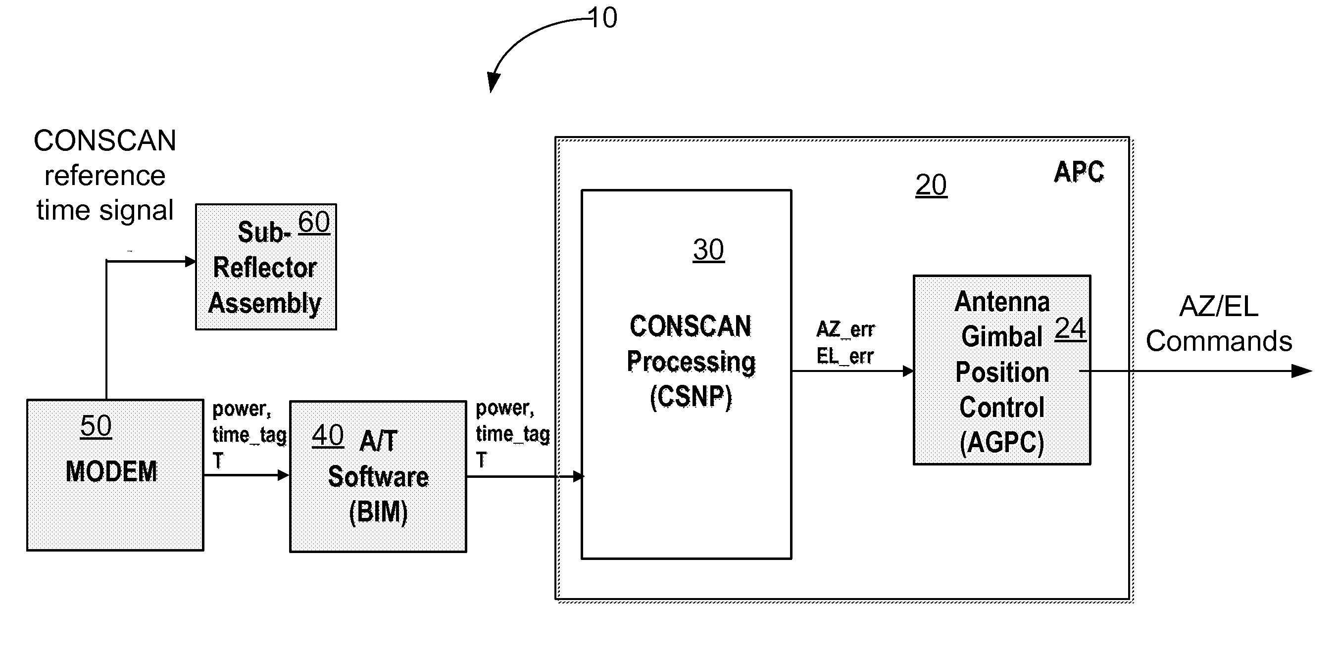
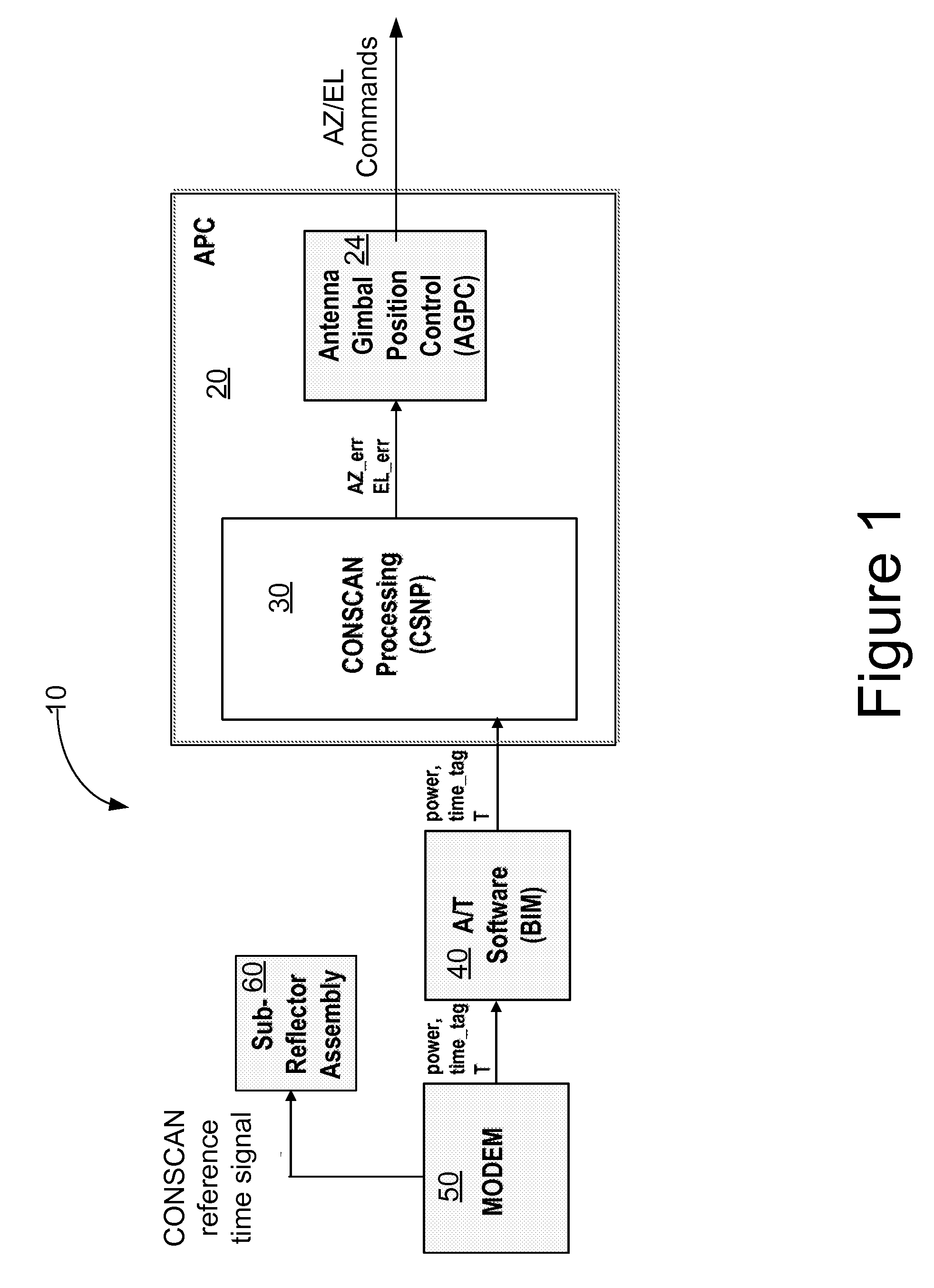
[0035]FIG. 1 illustrates one embodiment of an antenna boresight alignment system 10. The system 10 includes an antenna position control (APC) 20. The APC 20 is in communication with a MODEM 50. The MODEM 50 also communicates with an antenna sub-reflector assembly 60. Some embodiments of alignment system 10 may include an acquisition and tracking process 40. The acquisition and tracking process 40, if included, typically acts as a relay between the MODEM 50 and the APC 20.

[0036]In the illustrated embodiment, the APC 20 includes a conical scan (CONSCAN) processing (CSNP) system 30 and may include an antenna gimbal position control (AGP...


PUM


Abstract

Methods, systems and devices are disclosed for positioning an antenna having a sub-reflector assembly. A conical scan processor receives a period for a reference time pulse and a time tag. The processor calculates a rotation angle of the sub-reflector assembly using the received period for the reference time pulse and the received time tag. The processor may also receive a power measurement associated with the time tag. The processor may calculate and then output antenna boresight errors based on the calculated rotation angle of the sub-reflector assembly and the power measurements associated with the time tag.

Description

STATEMENT REGARDING FEDERALLY SPONSORED RESEARCH OR DEVELOPMENT[0001]The U.S. Government has a paid-up license in this invention and the right in limited circumstances to require the patent owner to license others on reasonable terms as provided for by the terms of Contract Number FAB-T F19628-02-C-0048 awarded by Electorinic Systems Center, Air Force Material Command, USAF.BACKGROUND OF THE INVENTION[0002]1. Field of the Invention[0003]The invention relates to methods, equipment and systems used to align antennas or laser communication equipment and, more particularly, to methods, equipment and systems used to obtain precision boresight error estimates and using these estimates to align antennas or laser communication equipment.[0004]2. Description of the Related Art[0005]Systems, equipment and methods have been developed to align an antenna's boresight. Some of these methods or algorithms estimate the antenna boresight error. However, these methods or algorithms are limited to the...

Claims


Application Information

Patent Timeline
Patent Type & Authority Applications(United States)
IPC IPC(8): H01Q3/00
CPCH01Q3/10
Inventor WU, YEONG-WEI A.
Owner THE BOEING CO
Why Eureka
Try Eureka