Satellite antenna

A technology of satellite antenna and high-frequency head, which is applied in the field of satellite antenna, can solve the problems of lack of automatic control of polarization axis, reduce the flexibility of antenna polarization control, etc., and achieve the effect of improving flexibility

Inactive Publication Date: 2015-03-04
HARXON CORP
View PDF4 Cites 2 Cited by
  • Summary
  • Abstract
  • Description
  • Claims
  • Application Information

AI Technical Summary

Problems solved by technology

Since the signal in the pitch and yaw directions needs to be sampled during the conical scanning process, and the position of the sampling point is related to the position of the optocoupler, the satellite antenna usually requires the position of the optocoupler to be fixed during the working process, which makes this antenna usually It is a two-axis form (pitch and yaw automatic control), but lacks the automatic control of the polarization axis. The polarization axis refers to the polarization angle of the high frequency head, which reduces the flexibility of antenna polarization control

Method used


Image

  • Satellite antenna
  • Satellite antenna

Examples


Embodiment Construction

[0013] In order to make the technical problems, technical solutions and beneficial effects to be solved by the present invention clearer and clearer, the present invention will be further described in detail below in conjunction with the accompanying drawings and embodiments. It should be understood that the specific embodiments described here are only used to explain the present invention, not to limit the present invention.

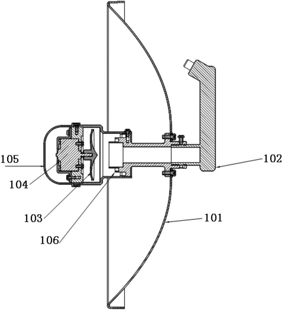
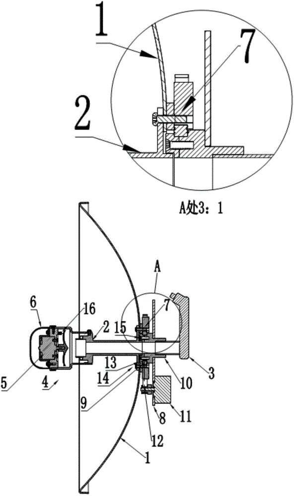
[0014] Such as figure 2 As shown, it is a schematic diagram of an embodiment of a satellite antenna provided by the present invention. The satellite antenna includes a parabolic surface 1, a waveguide 2, a tuner 3, a secondary reflector 4, a conical scanning motor 5, a protective cover 6, and the tuner is fixed. Device 10, polarized motor 11, conveyor belt 12, bearing fixing device 13, optocoupler 16. The conical scanning motor 5 is fixed on the protective cover 6, and is used to drive the secondary reflector 4 to rotate to realize conical scanning. ...


PUM


Abstract

The invention relates to the field of antennas, and provides a satellite antenna. The satellite antenna comprises a paraboloid, a waveguide, a tuner, a subreflector, a conical scanning motor, a protecting cover, a tuner fixing device, a polarizing motor, a conveyor belt, a bearing fixing device and an optical coupler; the conical scanning motor is fixed to the protecting cover and used for driving the subreflector to rotate to realize conical scanning; the optical coupler is fixed to a fixed conical scanning motor board; the protecting cover is fixed to the radiating end surface of the waveguide; the other end of the waveguide is connected with the paraboloid; the tuner is fixed to the tuner fixing device; the polarizing motor is arranged on the outer surface of the paraboloid and used for driving the tuner to rotate through the conveyor belt. According to the technical scheme, the satellite antenna has the advantage that the polarizing motor can be simply rotated to enable the rotating of a tuner polarizing angle, and therefore, the problem caused by a polarizing shaft of the satellite antenna can be solved, and the satellite searching flexibility of the satellite antenna can be improved.

Description

technical field [0001] The invention relates to the field of antennas, in particular to a satellite antenna. Background technique [0002] In the shipborne satellite antenna, the support frame is replaced by the combination of the secondary reflector and the waveguide to reduce the gain loss and the installation error, such as figure 1 Shown, is the sectional view of satellite antenna, and this satellite antenna comprises parabolic surface 101, tuner 102, secondary reflector 103, conical scanning motor 104, housing 105, waveguide 106 and optocoupler (not shown in the figure); Conical scanning motor 4 Drive the sub-reflector 3 to rotate at a high speed to realize conical scanning and tracking satellites. Since the signal in the pitch and yaw directions needs to be sampled during the conical scanning process, and the position of the sampling point is related to the position of the optocoupler, the satellite antenna usually requires the position of the optocoupler to be fixed ...

Claims


Application Information

Patent Timeline
Patent Type & Authority Applications(China)
IPC IPC(8): H01Q1/42H01Q3/02H01Q19/10H01Q15/24
Inventor 王春华易广为
Owner HARXON CORP
Why Eureka
Try Eureka