

Solenoid valve
a solenoid valve and valve body technology, applied in the direction of valve operating means/releasing devices, mechanical equipment, transportation and packaging, etc., can solve the problems of driving and passengers of motor vehicles, inconvenience for drivers and passengers, permanent impairment of health, etc., and achieve the effect of less weight and more compactness
- Summary
- Abstract
- Description
- Claims
- Application Information
AI Technical Summary
Benefits of technology
Problems solved by technology
Method used
Image

Examples
first embodiment
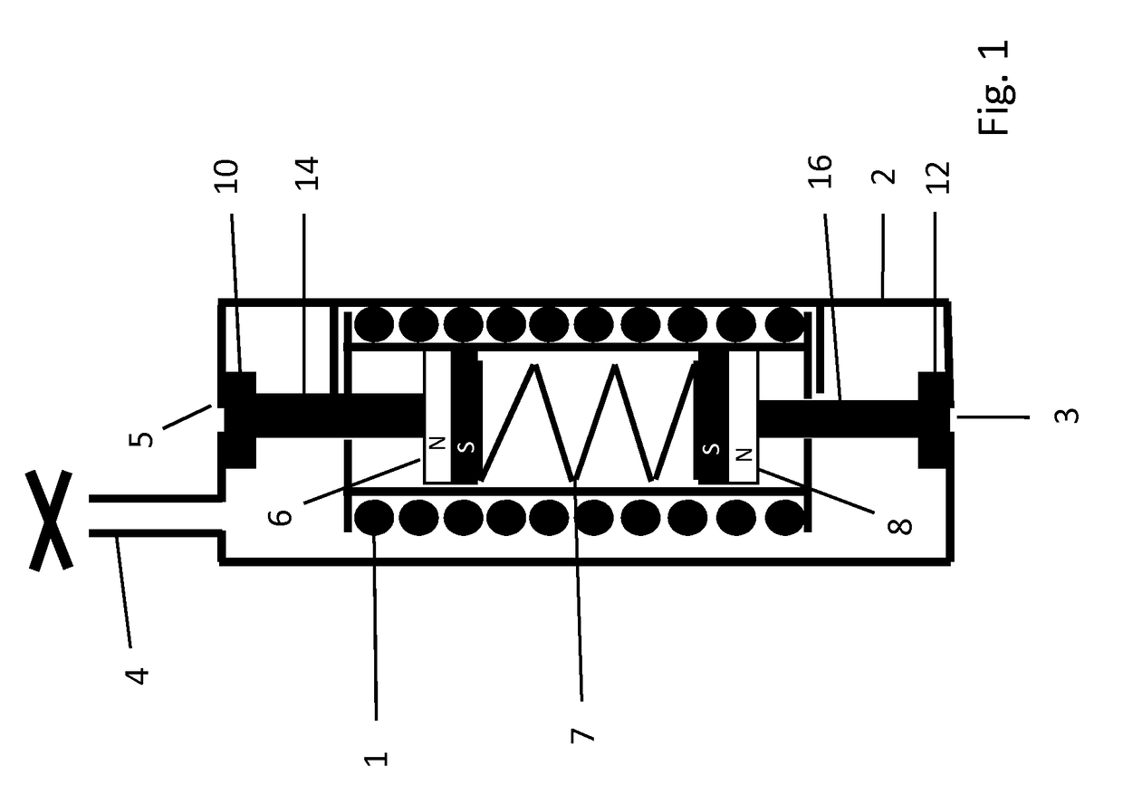
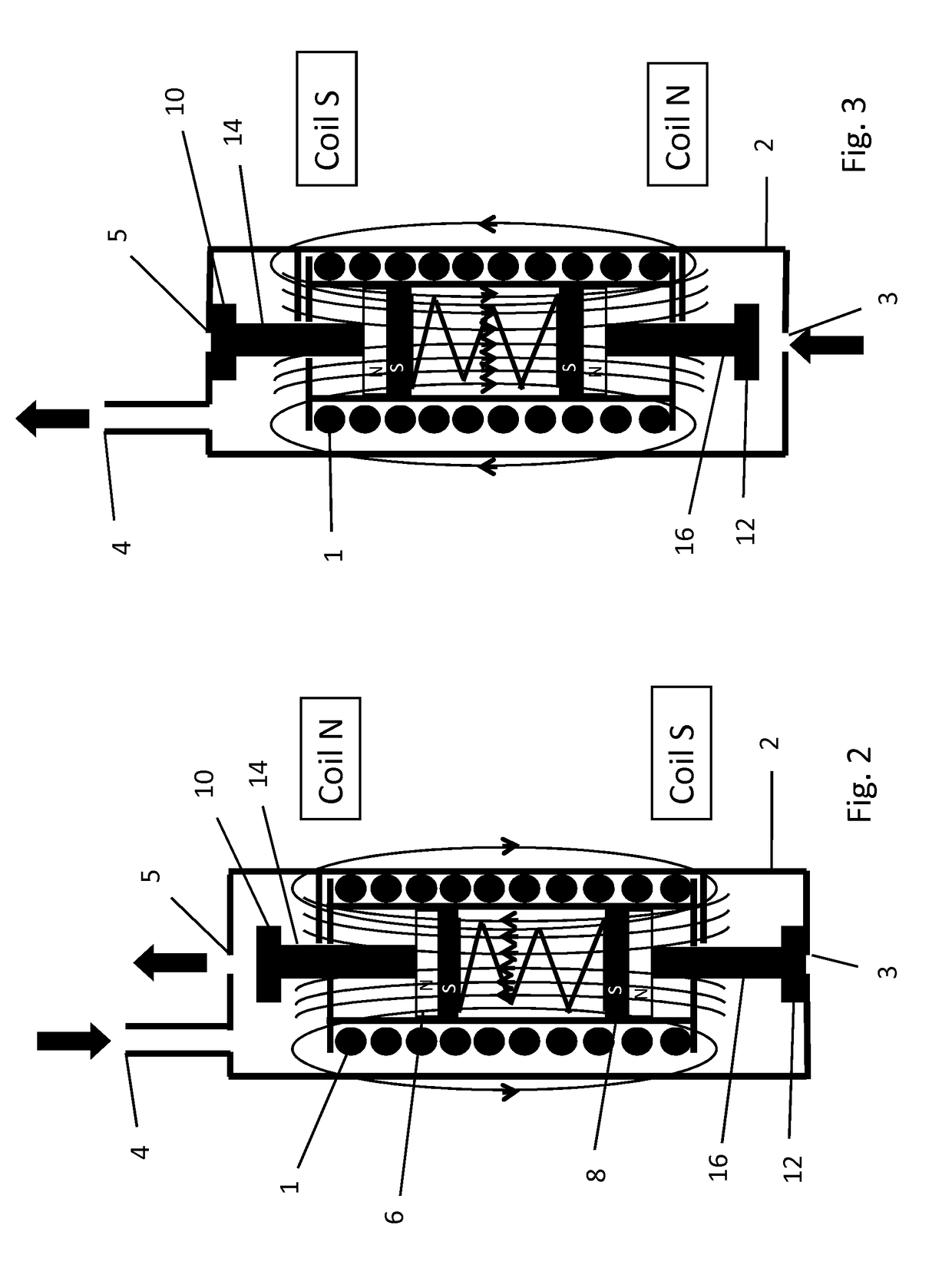
[0030]FIGS. 1 to 3 show the solenoid valve, wherein the design and components of the solenoid valve will first be described in connection with FIG. 1 which shows the valve in the inactivated state. The solenoid valve has a housing 2 with an input port 3 through which pressurized air is supplied if the input port is open. The housing 2 further has a first output port 4 which is connected to an air cell. A second output port 5 in communication with the environment at most sleeve. In the inactivated state of the valve the input port 3 is closed by a sealing tip 12 which is disposed at the end of an input plunger rod 16. Correspondingly, the second output port 5 is closed by an output sealing tip 10 which is disposed on an output plunger rod 14. The output plunger rod 14 is connected to a first permanent magnet 6 which is disposed at a position in the upper half of the solenoid coil 1. The input plunger rod 16 is connected to a second permanent magnet 8 which is disposed at a position i...
second embodiment
[0033]In FIG. 4 the solenoid valve is shown in the inactivated state. In this case the first and second permanent magnets 6, 8 in the interior of the solenoid coil 1 are connected. The first permanent magnet 6 is connected to the output sealing tip 10 by an upwardly extending cord 22. The second permanent magnet 8 is connected to the input sealing tip 12 by a downwardly extending cord 24. The length of the cords 22, 24 are such that they are under no attention when the solenoid valve is in the inactivated state shown in FIG. 4. In this state the output sealing tip 10 and the input sealing tip 12 are pressed to the respective valve ports by respective springs 7.
[0034]In FIG. 5 a voltage is supplied to the solenoid coil 1 which leads to the generation of a magnetic field of a first polarity, namely with the north pole of the magnetic field pointing to the upper end of the solenoid coil and the south pole pointing to the lower end of the solenoid coil. As described in connection with F...
fourth embodiment
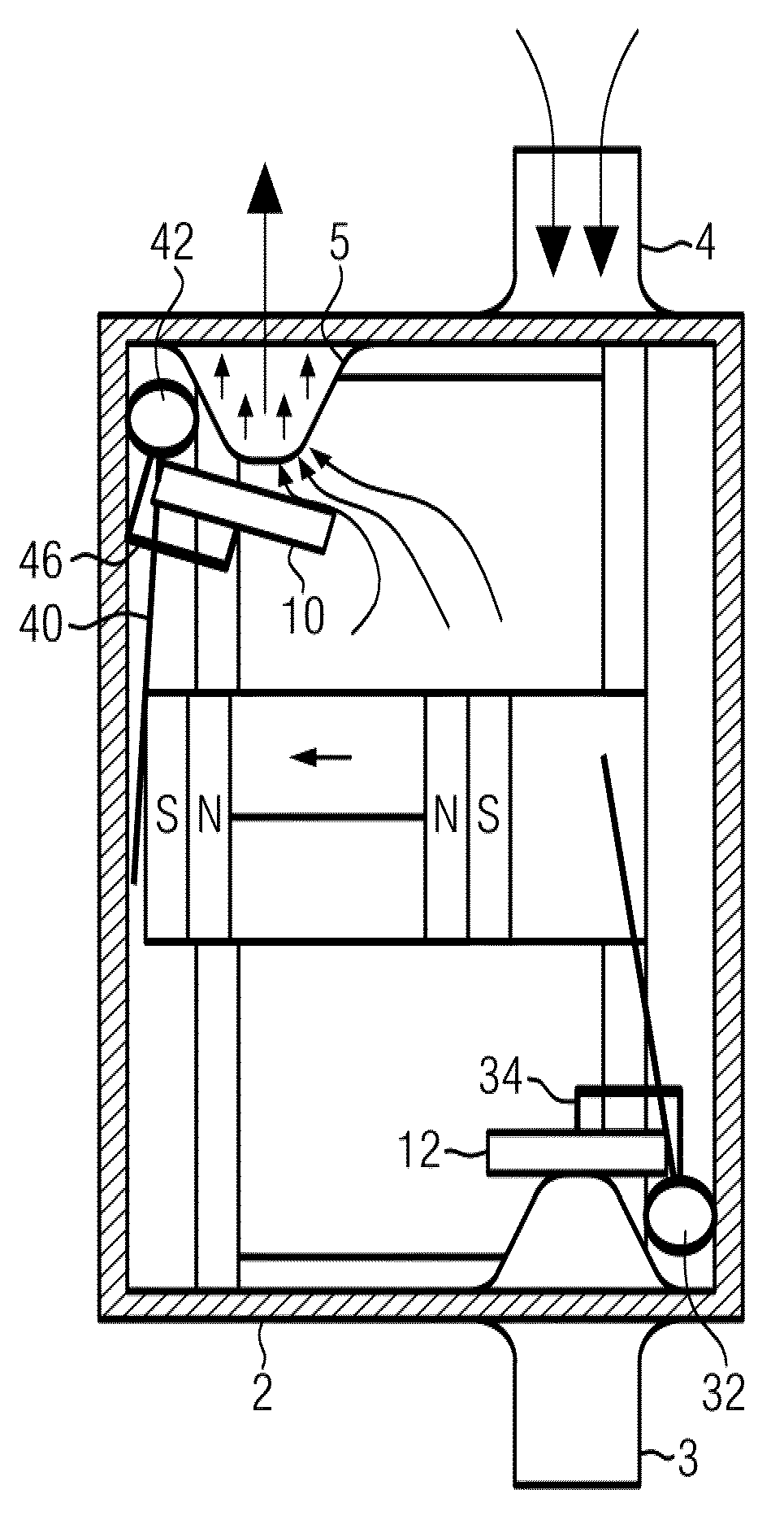
[0039]FIGS. 11 to 13 show simplify schematical views of a fourth embodiment in the inactivated state, with a voltage of first polarity applied to the solenoid coil, and with a voltage of opposite polarity, respectively. In this embodiment again two permanent magnets are located with oppositely directed poles within the inner space of the solenoid coil 1. At the first end of the solenoid coil there is located first a transverse lever 30 which extends from the opening of the solenoid coil and further to a first actuation shaft 32 which is rotateably mounted in the housing 2 of the valve. A first actuation lever 34 is connected to the first actuation shaft 32 and carries the input sealing tip 12.
[0040]At the opposite end of the solenoid coil 1 there is a corresponding arrangement of a second transverse lever 40, a second actuation shaft 42, and a second actuation lever 46 which is connected to the output sealing tip 10.
[0041]If the first and second permanent magnets are moved by a firs...
PUM
 Abstract
Description
Claims
Application Information