
Autostereoscopic display system

Inactive Publication Date: 2017-05-25
KONINKLJIJKE PHILIPS NV
View PDF4 Cites 4 Cited by
  • Summary
  • Abstract
  • Description
  • Claims
  • Application Information

AI Technical Summary

Benefits of technology

The invention is a display that shows 3D images without the need for special glasses. It can be used for a wide range of applications, including research, games, advertising, and even flight simulators. The technical benefits are improved accessibility and more realistic viewing experiences.

Problems solved by technology

However, several problems are associated with the device.
Another problem is that the vertically aligned lens results in a reduction in resolution in the horizontal direction only, while the resolution in the vertical direction is not altered.
Thus the resolutions in horizontal and vertical direction are not balanced ideally.
This results in a low color performance and even grayscale inversion.

Method used


Image

  • Autostereoscopic display system
  • Autostereoscopic display system
  • Autostereoscopic display system

Examples


Embodiment Construction

[0053]While this invention is susceptible of embodiment in many different forms, there is shown in the drawings and will herein be described in detail one or more specific embodiments, with the understanding that the present disclosure is to be considered as exemplary of the principles of the invention and not intended to limit the invention to the specific embodiments shown and described.

[0054]For typical landscape displays, the horizontal row lines serve as address lines and the vertical column lines serve as data lines. Row lines are also referred to as address lines; their control units are called row drivers. Their control units of the vertical column lines are called column drivers. Typically a display has multiple row and column drivers, each connected with a row or column lines. The terms row line and column line are less clear for devices such as tablets that are operable in portrait and landscape mode. For this reasons, this document uses the term data line to refer to a c...


PUM


Abstract

An autostereoscopic display system (240) arranged to display an autostereoscopic image, the display system comprising a display panel (400, 500) comprising multiple sub-pixels. The multiple sub-areas of a sub-pixel comprising a high-intensity sub-area, wherein the high-intensity sub-area is arranged to provide light of a higher intensity than the other sub-areas in the multiple sub-areas of the sub-pixel for at least one image value received in the sub-pixel. The high-intensity sub-area may be arranged in the sub-pixel to reduce banding, inter alia, by splitting the multiple sub-areas along a direction parallel to the direction of the columns.

Description

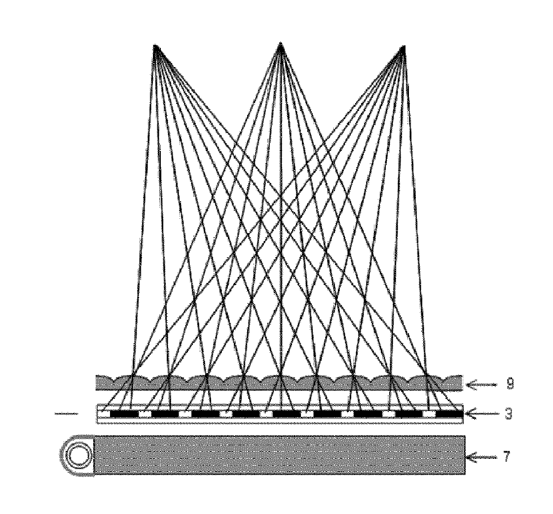
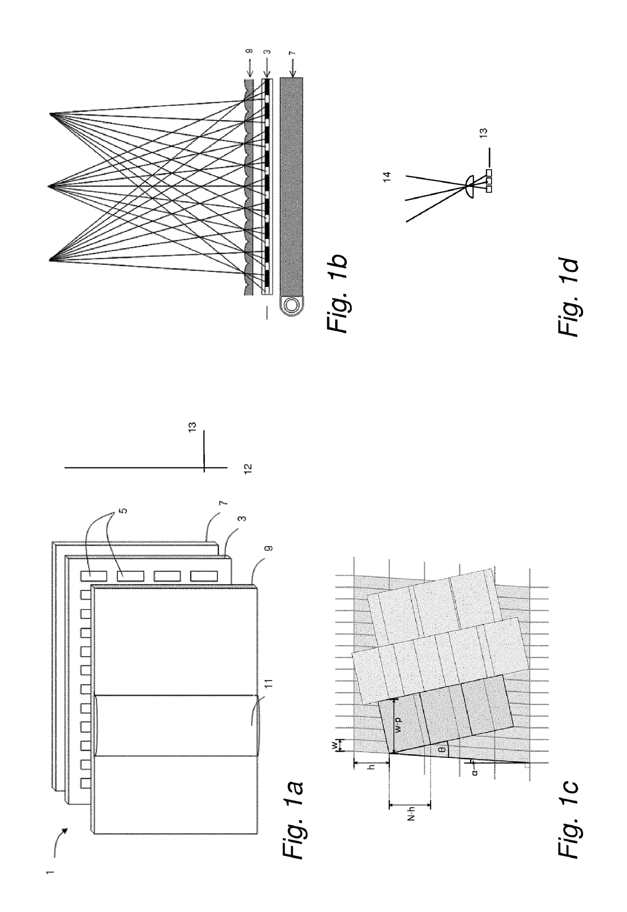
FIELD OF THE INVENTION[0001]The invention relates to an autostereoscopic display system and to a display panel.BACKGROUND[0002]A known autostereoscopic display device comprises a two-dimensional liquid crystal display panel having a row and column array of display pixels acting as an image forming means to produce a display. An array of elongated lenses extending parallel to one another overlies the display pixel array and acts as a view forming means. These are known as “lenticular lenses”. Outputs from the display pixels are projected through these lenticular lenses, which function to modify the directions of the outputs.[0003]The lenticular lenses are provided as a sheet of lens elements, each of which comprises an elongate partly-cylindrical (e.g. semi-cylindrical) lens element. The lenticular lenses extend in the column direction of the display panel, with each lenticular lens overlying a respective group of two or more adjacent columns of display sub-pixels.[0004]Each lenticul...

Claims


Application Information

Patent Timeline
IPC IPC(8): H04N13/04G02B27/22G02B30/29
CPCH04N13/0404H04N13/0415H04N13/0422H04N2013/0077G09G3/3611G09G2320/0626G02B27/2214G09G2300/0443G09G2300/0452G09G2320/0242G09G2320/0673G09G3/003G02B30/27G09G3/3648H04N13/305H04N13/324H04N13/317G02B30/29
Inventor VAN PUTTEN, EIBERT GERJANJOHNSON, MARK THOMASKROON, BART
Owner KONINKLJIJKE PHILIPS NV
Learn More