

Inkjet printing device and printing method
a printing device and printing method technology, applied in printing, printing, power drive mechanisms, etc., to achieve the effect of reducing banding and high-quality print images
- Summary
- Abstract
- Description
- Claims
- Application Information
AI Technical Summary
Benefits of technology
Problems solved by technology
Method used
Image

Examples
first embodiment
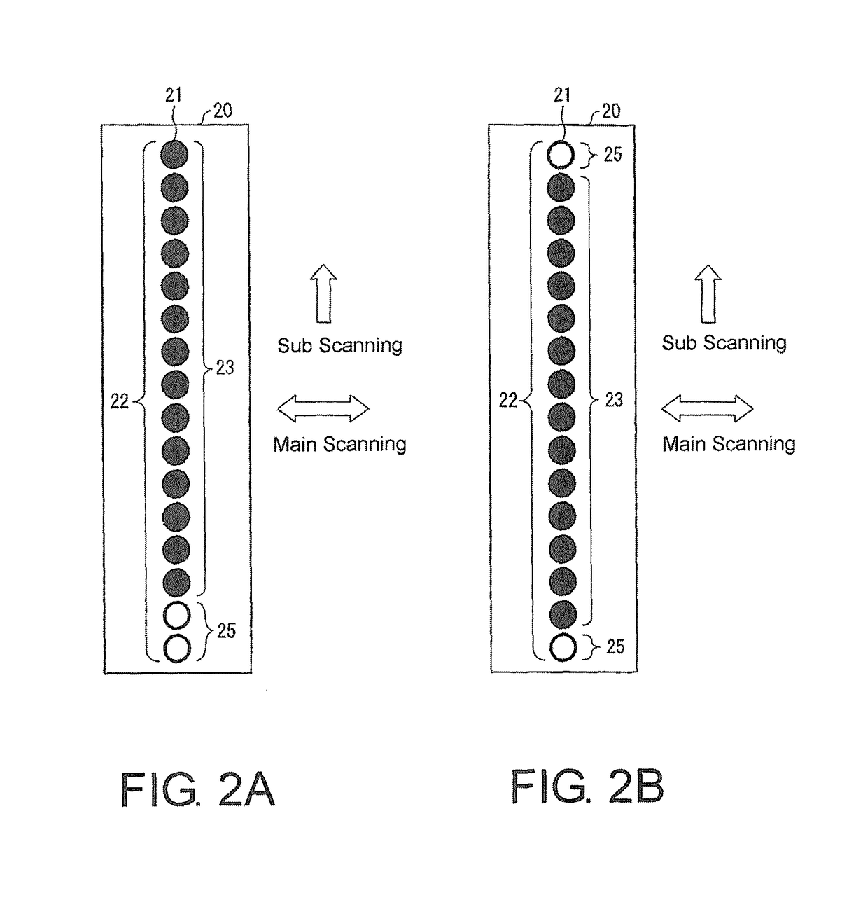
[0036]In explaining one embodiment (first embodiment) of the present invention based on FIG. 1, FIG. 2A and FIG. 2B, and FIG. 3A and FIG. 3B, such explanation will be as follows.
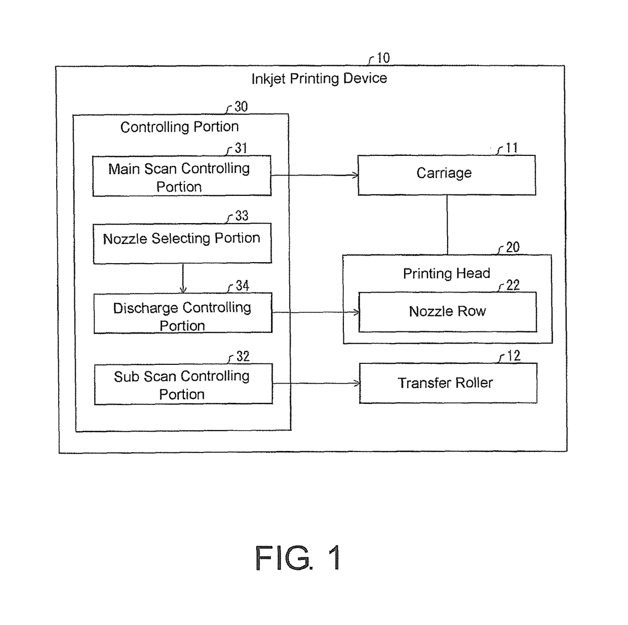
[0037]FIG. 1 is a functional block diagram showing an overview configuration of an inkjet printing device 10 according to an embodiment of the present invention. As shown in FIG. 1, an inkjet printing device 10 includes a carriage 11, a transfer roller 12, a printing head 20, and a controlling portion 30. The controlling portion 30 is provided with a main scan controlling portion (main scan controlling unit) 31, a sub scan controlling portion (sub scan controlling unit) 32, a nozzle selecting portion (nozzle selecting unit) 33 and a discharge controlling portion 34.
[0038]The carriage 11 is equipped with the printing head 20, and is configured movable. The main scan controlling portion 31 causes the printing head 20 to scan in a main scanning direction by controlling the carriage 11.
[0039]The transfer roller ...
second embodiment
[0056]In explaining another embodiment (second embodiment) of the present invention based on FIG. 4, FIG. 5A, and FIG. 5B, such explanation will be as follows. It should be noted that for the sake of convenience of explanation, components having the same function as that described in the previous embodiment will be given the same reference signs, and the explanation thereof will be omitted.
[0057]FIG. 4 is a schematic diagram showing an example of an overview configuration of a printing head 20 of the present embodiment. As shown in FIG. 4, in the present embodiment, the printing head 20 includes a plurality of the nozzle rows 22 that discharges a same color ink.
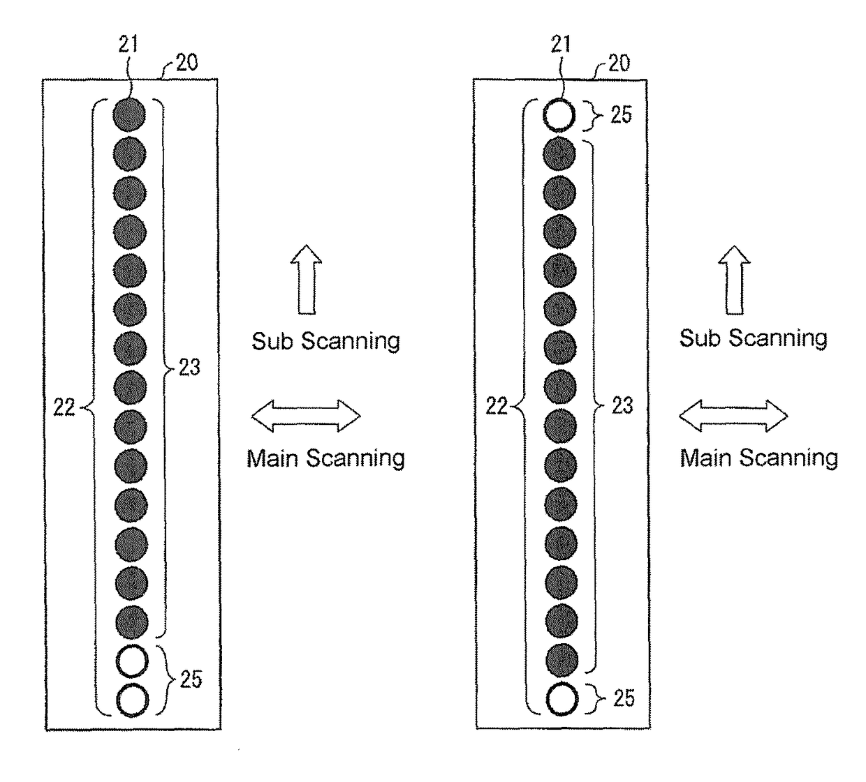
[0058]FIG. 5A and FIG. 5B are diagrams for explaining a manner of printing in the present embodiment, where FIG. 5A shows an example of a range in the sub scanning direction that the respective nozzle rows 22 can perform printing in one scan, and FIG. 5B shows an example of the print image printed by the one scan. Specificall...
third embodiment
[0063]In explaining another embodiment (third embodiment) of the present invention based on FIG. 6A and FIG. 6B, such explanation will be as follows. It should be noted that for the sake of convenience of explanation, components having the same function as that described in the previous embodiments will be given the same reference signs, and the explanation thereof will be omitted.
[0064]FIG. 6A and FIG. 6B are diagrams for explaining a manner of printing in the present embodiment, where FIG. 6A shows an example of a range in the sub scanning direction that the nozzle row 22 can perform printing in each scan, and FIG. 6B shows an example of the print image printed by plural scans. Specifically, in FIG. 6A, “1” to “6” denote a range in which the nozzle row 22 can perform printing in the sub scanning direction in corresponding one of first to sixth scans. In FIG. 6B, “1” to “6” denote that regions thereof are printed in corresponding one of the first to sixth scans. It should be noted ...
PUM
 Abstract
Description
Claims
Application Information