Ink container

a technology of ink containers and ink, which is applied in the direction of paper/cardboard containers, separation processes, instruments, etc., can solve the problems of ink precipitation, ink used in printing devices may change with time in ink containers, foreign matter mixing, etc., and achieve stable operation of printing devices, stable high-quality print images, and the effect of reducing the flow ou

Active Publication Date: 2007-03-01
RISO KAGAKU CORP
View PDF7 Cites 8 Cited by
  • Summary
  • Abstract
  • Description
  • Claims
  • Application Information

AI Technical Summary

Benefits of technology

[0023] (1) In spite of ink container body contraction which will be caused by ink flow out through the ink supply opening, the shape and volume of the region for residual ink liquid are kept on and do not suffer any change under protection of shape retaining means. The no change of the region shape and volume ensures coarse-grained ink etc. stably to stay in the region for residual ink liquid and flowing out of coarse-grain ink etc. from the ink container body into a printing device decreases greatly.
[0024] (2) Because of the great decrease of the flowing out of coarse-grain ink etc. into the printing device, such clogging in the printing device, such as nozzle clogging of IJ heads in the printing device, pore clogging on a plate cylinder or a plate screen in the printing device, are almost prevented, and forming a stable high-quality print image and stable operation of the printing device may be obtained.

Problems solved by technology

In a case where ink is stored for a long period of time in an ink container, in a case where due to the low frequency of use of a printing device, the ink in the ink container mounted on the printing device is not consumed for a long period of time, and in other cases, the ink used in the printing device may sometimes change with time in the ink container.
(b) Also, there is a case where foreign matter which has mixed during the manufacturing of ink precipitates in the ink container.
However, this ink bag is of such a simple construction that the ink bag contracts and is deformed as ink is consumed and the top and bottom plates of the ink bag only suppress the dancing of the ink bag.
Therefore, precipitates of coarse-grained ink etc. standing on the bottom of the ink bag flow out of the ink bag due to the contraction and deformation and are supplied to the printing device, and it is difficult to make coarse-grained ink etc. remain in the ink bag.
However, this supporting member only reinforces the ink container body and only prevents the deformation of the ink container body which might be caused by taking the content (ink) out of the ink container body.
However, the outer box only constrains part of the inner bag.
If precipitates of coarse-grained ink etc. as described above flow out of the ink container to the printing device and supplied to the device, the following troubles occur.
In a case where the printing device is an IJ printer (“IJ” means ink jet; IJ will be hereinafter used as ink jet), during the passage of coarse-grained ink through fine pores of an IJ head, the coarse-grained ink impedes the formation of an ink meniscus in the IJ head and appropriate ink discharge is impossible.
In some cases, the pores of the IJ head become clogged with the coarse-grained ink, thereby causing the trouble that an appropriate print image cannot be obtained.
In the worst case, fine pores of the IJ printer become clogged with the coarse-grained ink and the IJ printer itself does not work normally and is brought into an unusable condition.
In a case where the printing device is a stencil printing device, when coarse-grained ink passes through pores of an ink-passing body of a printing cylinder, such as a plate cylinder and a screen, the pores are clogged with the coarse-grained ink, thereby causing the trouble that an appropriate print image cannot be obtained.
In the worst case, fine pores of the stencil printing device become clogged with the coarse-grained ink and the stencil printing device itself does not work normally and is brought into an unusable condition.

Method used


Image

  • Ink container
  • Ink container
  • Ink container

Examples


Embodiment Construction

[0025] Hereinafter, the best mode for carrying out the invention will be described in detail with reference to the accompanying drawings.

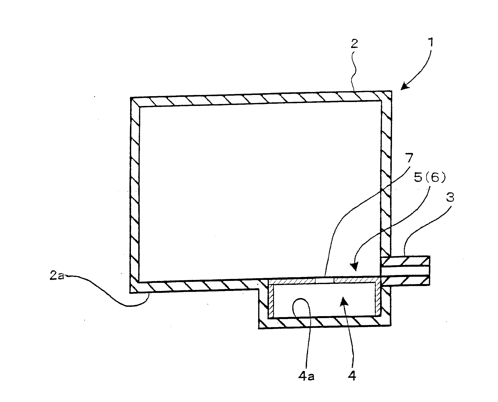
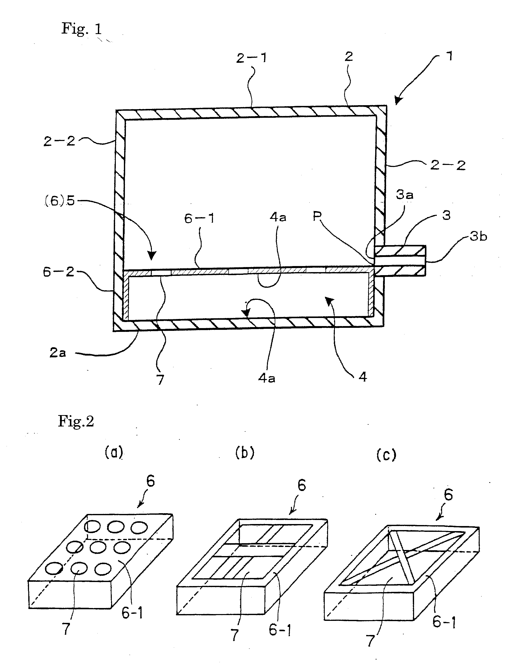
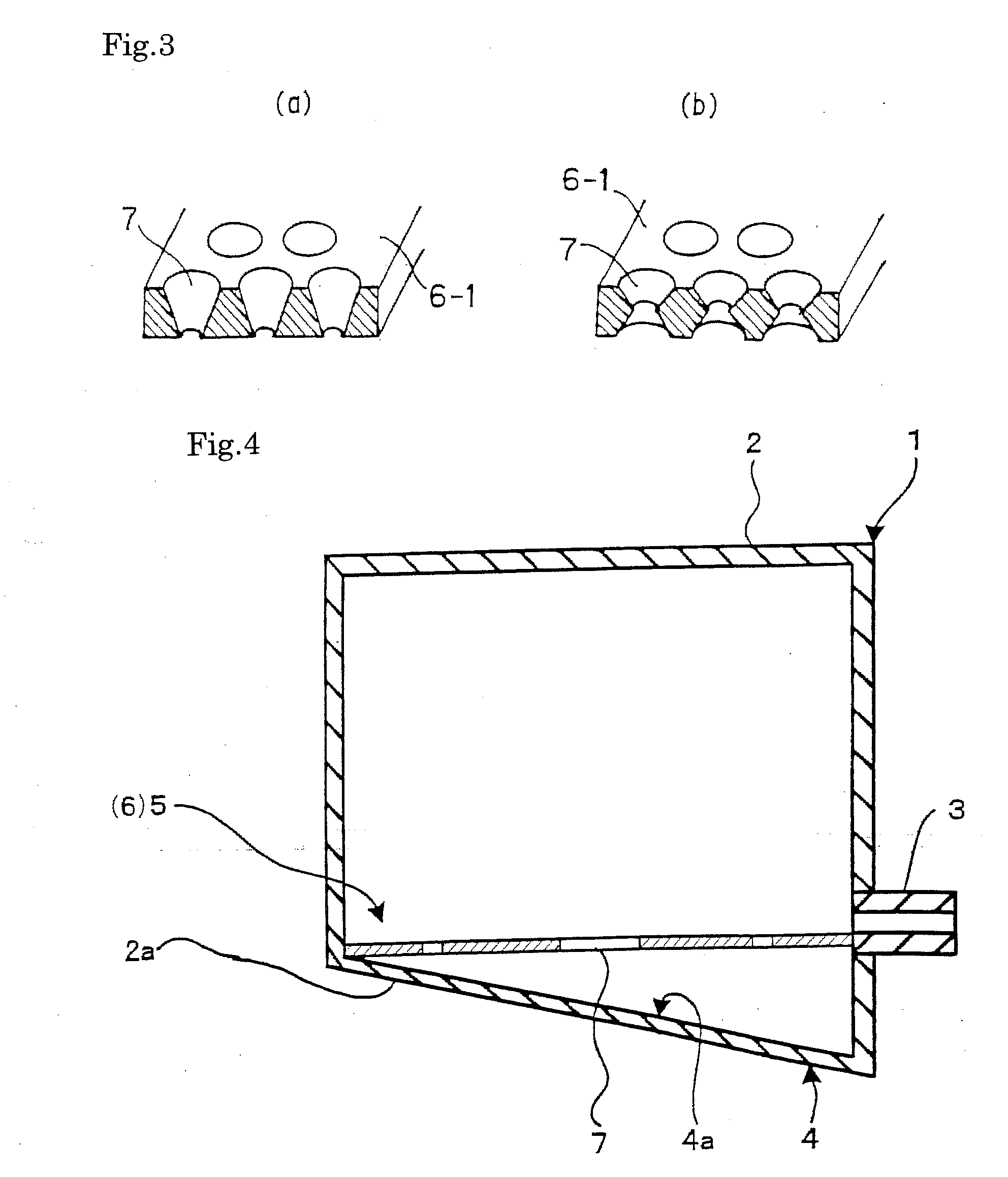
[0026] An ink container 1 shown in FIG. 1 is provided with a bag-like ink container body 2, and this bag-like ink container body 2 is formed from a sheet which itself has flexibility. Ink which is used by a printing device, which is not shown, is stored in this ink container body 2. In the case of this embodiment, this ink container body 2 has the shape of a rectangular parallelepiped as shown in FIG. 1 or a shape close to this shape when the ink container body 2 is filled up with ink.

[0027] An ink supply opening 3 is provided on the bottom 2a side of the ink container body 2. This ink supply opening 3 is disposed in a position a little higher than a bottom 2a of the ink container body 2 and integrally fixed to the ink container body 2. The side of one opening end 3a (one end) of the ink supply opening 3 communicates with the inside of the ink co...


PUM


Abstract

Provided is an ink container suitable for forming a stable high-quality print image and obtaining stable operation of a printing device by enabling precipitates of coarse-grained ink etc. standing in an ink container body to be left in the ink container body and by eliminating troubles due to the supply of such precipitates of coarse-grained ink etc. to the printing device. A region for residual ink liquid 4 and a sheet-entry preventing member 6 as shape retaining means 5 are provided on the bottom 2a side of a bag-like ink container body 2 formed from a flexible sheet. The region for residual ink liquid 4 is disposed in a position lower than one end 3a of an ink supply opening part 3 fixed to the ink container body 2. When the sheet composing the ink container body 2 moves, the sheet-entry preventing member 6 prevents the sheet from entering the region for residual ink liquid 4, thereby keeping the shape and volume of the region part for residual ink liquid 4.

Description

TECHNICAL FIELD [0001] The present invention relates to an ink container which is used by being mounted on a printing device and, more particularly, to an ink container which enables precipitates of coarse-grained ink etc. standing in an ink container body to be positively left in the ink container body. BACKGROUND ART [0002] In a case where ink is stored for a long period of time in an ink container, in a case where due to the low frequency of use of a printing device, the ink in the ink container mounted on the printing device is not consumed for a long period of time, and in other cases, the ink used in the printing device may sometimes change with time in the ink container. [0003] For example, (a) in the case of pigment ink, coarse-grained ink is generated due to the condensation of a pigment, and this coarse-grained ink precipitates in the ink container. (b) Also, there is a case where foreign matter which has mixed during the manufacturing of ink precipitates in the ink contai...

Claims


Application Information

Patent Timeline
Patent Type & Authority Applications(United States)
IPC IPC(8): B41J2/175B41L13/18
CPCB41L13/18B41J2/17513
Inventor WAKAYAMA, TAKAHIRO
Owner RISO KAGAKU CORP
Why Eureka
Try Eureka