Method and Apparatus for Leakage Flux Testing

a leakage flux and flux technology, applied in the direction of material magnetic variables, etc., can solve the problem that the high spatial resolution of individual probes, in general, cannot be fully achieved, and achieve the effect of increasing the relevance of further processing signals

Active Publication Date: 2017-06-08
INSTITUT DR FORSTER
View PDF4 Cites 8 Cited by
  • Summary
  • Abstract
  • Description
  • Claims
  • Application Information

AI Technical Summary

Benefits of technology

[0024]All probes of a probe array may be arranged next to one another in a single straight row in the first direction (width direction). The effective widths of adjacent probes may overlap on account of the finite testing distance. It is also possible to subdivide the probes into two (or more) mutually parallel rows and arrange these offset to one another in the width directions in such a way that the probes sit “in gaps”. As a result, a coverage without gaps of the entire width to be tested is possible in the width direction.
[0025]In particular, Hall probes or MR probes (probes which use a magnetoresistive effect for magnetic field detection, e.g. GMR (giant magnetoresistance), AMR (anisotropic magnetoresistance), CMR (colossal magnetoresistance) or TMR (tunnel magnetoresistance)) or inductive probes (in particular coils) or any other type of magnetic-field-sensitive probes may be considered as probes.
[0026]In order, where possible, only to process those signals in the subsequent signal processing which may in fact have relevance for the testing situation, provision is made in some variants of the method for pre-filtering of the probe signals in the apparatus, carried out before the mapping operation, by means of a band-pass filter with adjustable limit frequencies. Here, a lower limit frequency is set to a lowest frequency of the probe signals to be expected and an upper limit frequency is set to a highest frequency of the probe signals to be expected. As a result, coarse pre-filtering is possible. The limit frequencies may be adjusted depending on the pass-over speed of the probe, the testing distance, the smallest and largest fault width and fault depth to be detected, optionally on the wall thickness (in the case of pipes), and possibly on other boundary conditions. As a result, the testing may be matched to specific testing conditions, some sources of disturbance are removed from the signals and the relevance of the further processed signals is increased. By way of example, low-frequency signal components which carry no information relevant to the material to be tested during the testing situation may be removed by suitable pre-selection of a lower limit frequency. By way of example, the highest limit frequency may be set in such a way that frequencies which are higher than those frequencies which typically originate from small cracks on the surface of the material to be tested are filtered out. From experience, it is said frequencies of small cracks which provide the highest relevant frequency components.

Problems solved by technology

In the case of probe widths of individual probes of more than 10 mm, the sought-after high spatial resolution of the individual probes may, in general, no longer be fully achieved.

Method used


Image

  • Method and Apparatus for Leakage Flux Testing
  • Method and Apparatus for Leakage Flux Testing
  • Method and Apparatus for Leakage Flux Testing

Examples


Embodiment Construction

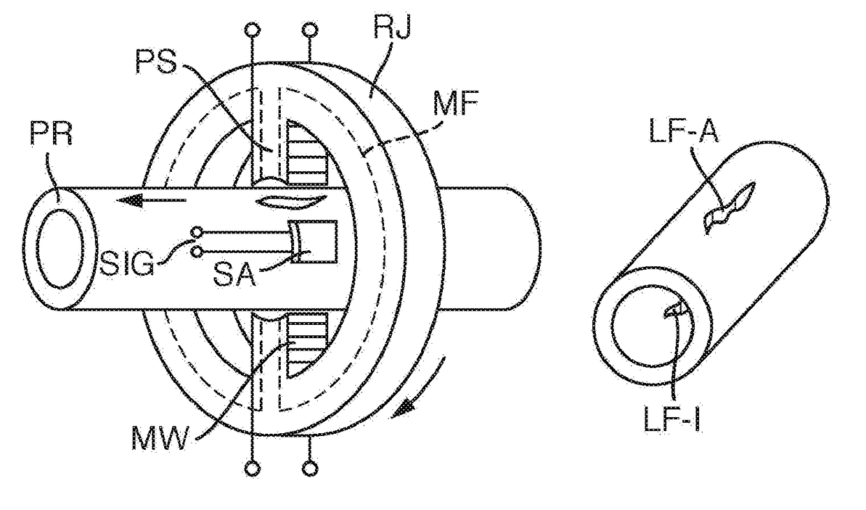
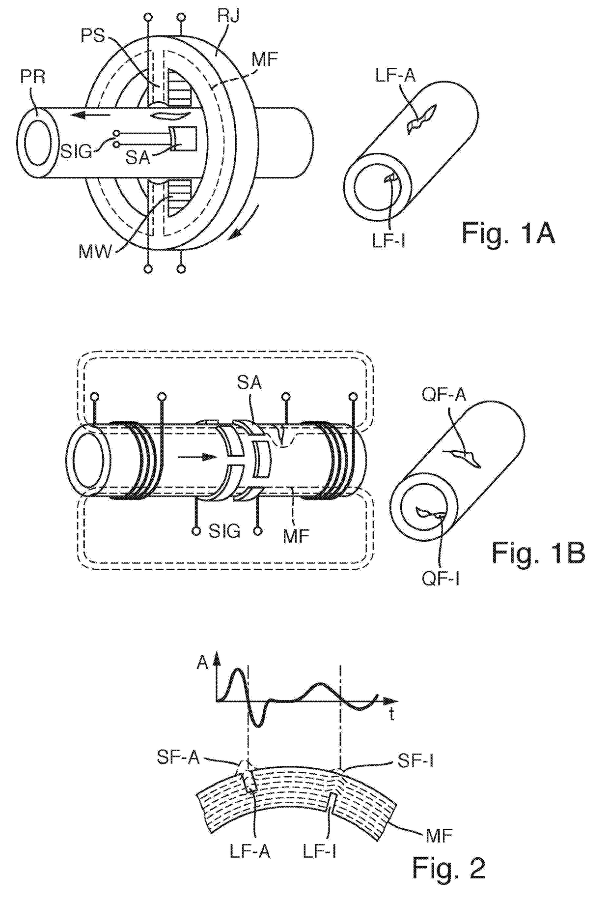
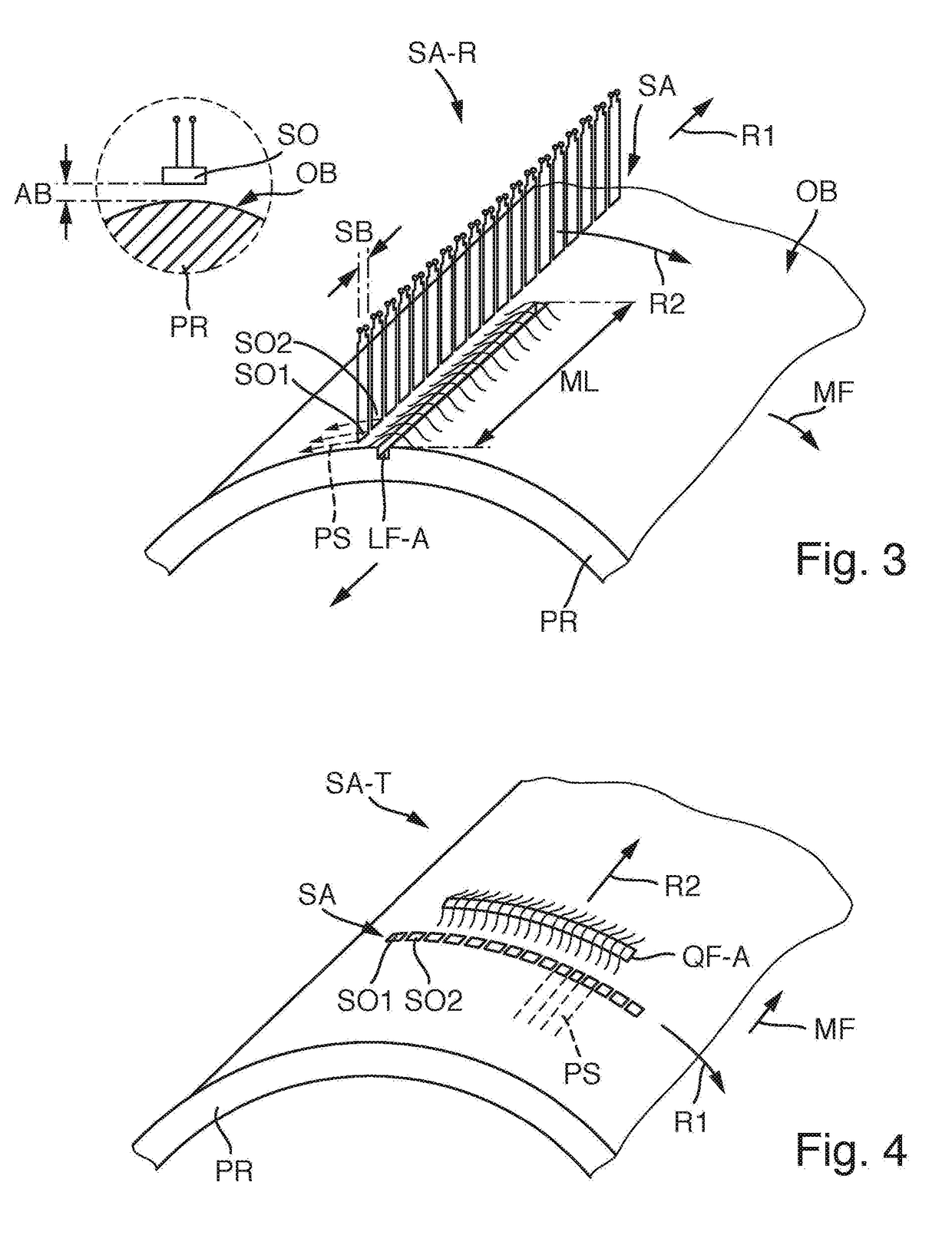
[0059]Below, exemplary embodiments of the claimed invention are explained on the basis of an apparatus for leakage flux testing of ferromagnetic material to be tested, in the form of hot-rolled ferromagnetic pipes in a continuous method. The apparatus is configured for the detection of defects or inadequacies or imperfections of different types and may, for example, reliably detect rolling faults both on the pipe inner side (inner fault) and on the pipe outer side (outer fault). In so doing, it is possible to reliably find and characterize longitudinal faults (faults with the main direction of extent parallel to the pipe longitudinal axis) and transverse faults (faults with the main direction of extent in the circumferential direction or perpendicular to the pipe longitudinal axis) and oblique faults (transversely to the longitudinal direction and to the circumferential direction).

[0060]In one embodiment, two partial systems are integrated in a multi-testing block. A rotating partia...


PUM

PropertyMeasurementUnit
widthaaaaaaaaaa
fault lengthaaaaaaaaaa

Abstract

In a method for leakage flux testing of ferromagnetic material to be tested, in particular ferromagnetic pipes, for detecting defects, a testing volume of the material to be tested is magnetized by a constant magnetic field. A surface of the material to be tested is scanned by a probe arrangement for capturing magnetic leakage fields caused by defects. The probe arrangement has a probe array with a multiplicity of magnetic-field-sensitive probes arranged next to one another in a first direction and held at a finite testing distance from the surface of the material to be tested during the testing. Electrical probe signals are evaluated for qualifying the defects. Use is made of a probe arrangement in which the probes each have a probe width in the first direction which lies in the range from 20% of the testing distance up to 10 mm. An evaluation of the probe signals includes a mapping operation, in which signal information representing the probe signal is linked to spatial information representing the creation location of a probe signal for each probe signal in order to form spatially dependent signal data, a matrix-forming operation, in which the spatially dependent signal data, or signal data derived therefrom, are stored in fields, assigned with the correct location, of a basis matrix, and at least one evaluating operation, in which spatially dependent signal data from at least two fields of the basis matrix, directly or indirectly adjacent to one another in an evaluating direction, are linked to one another using at least one evaluating algorithm.

Description

FIELD OF THE INVENTION[0001]The invention relates to a method for leakage flux testing of ferromagnetic material to be tested for detecting defects and to an apparatus, suitable for carrying out the method.BACKGROUND OF THE INVENTION[0002]Magnetic leakage flux methods are an important component of quality control, both in the production process and during the cyclically recurring testing of the finished parts, in nondestructive testing in respect of defects of semi-finished product and finished parts. In relation to some bothersome properties of the materials, such as roughness of the surface or scale coating in the case of hot-rolled products, magnetic leakage flux methods are less sensitive than e.g. the eddy current method or ultrasonic testing. As a result, there is a better ratio between used signal and noise signal (S / N ratio), as a result of which a more reliable fault detection is facilitated.[0003]In an apparatus for detecting defects by means of leakage flux measurement, a...

Claims


Application Information

Patent Timeline
Patent Type & Authority Applications(United States)
IPC IPC(8): G01N27/87
CPCG01N27/87
Inventor UHLIG, ROBERT P.HECKER, FRIEDRICH
Owner INSTITUT DR FORSTER
Why Eureka
Try Eureka