
Sole elements and shoes

a technology of sole elements and shoes, applied in the field of sole elements, can solve the problems of requiring toxic substances, affecting the effect of lateral extension, and insufficient insulation of shoes from their environment, etc., and achieve the effect of large lateral extension

Inactive Publication Date: 2017-06-15
ADIDAS
View PDF42 Cites 6 Cited by
  • Summary
  • Abstract
  • Description
  • Claims
  • Application Information

AI Technical Summary

Benefits of technology

The present invention provides a shoe that uses a deformable material to generate heat repeatedly as the wearer's foot touches the ground, ensuring that the feet are always warm. A transport element selectively directs the generated heat to the first portion, preventing heat diffusion and ensuring efficient heat transfer. The shoe's insulating layer is made of lightweight foam material that does not significantly change the weight of the shoe. The technical effects of the invention are improved shoe comfort, prevention of cold feet, and improved shoe performance.

Problems solved by technology

However, a mere insulation of a shoe from its environment may not be sufficient to keep certain regions of a foot warm, such as the toe region, especially when the shoe is used in a cold environment for a longer period of time.
However, creating heat by chemical reactions or phase change may require the need of toxic substances.
Moreover, such an approach is a one-time process, such that the chemical compound needs to be frequently replaced which may be costly and cumbersome.
However, also with this approach, the amount of energy that can be used to warm the foot remains limited.
When using the shoes in a cold environment, the stored heat may be used up quickly such that the feet may get cold over time.
The form parts are structured in such a way at respective opposing surfaces that, when the form parts move towards each other, surface friction occurs, which generates frictional heat.

Method used


Image

  • Sole elements and shoes
  • Sole elements and shoes
  • Sole elements and shoes

Examples


embodiment 1

2. Sole element , wherein a resilience of the deformable material is below 80%, preferably below 50%, particularly preferably below 15%.

3. Sole element according to embodiment 1 or embodiment 2, wherein the first portion comprises a resilient material (150, 160; 260) having a resilience that is higher than a resilience of the deformable material (121; 221; 321), preferably higher by at least 15%, particularly preferably by at least 25%, and / or having a resilience that is at least 20%, preferably at least 35%, particularly preferably at least 50%.

4. Sole element according to embodiment 3, wherein the resilient material (150, 160; 260) comprises a thermal conductivity below 100 mW / (K·m), preferably below 75 mW / (K·m), particularly preferably below 60 mW(K·m).

5. Sole element according to any of embodiments 1-4, wherein the deformable material (121; 221; 321) comprises a foam material, in particular a (poly-)urethane foam material.

6. Sole element according to any of embodiments 1-5, wher...

embodiment 30

31. Shoe , wherein the insulating layer is at least partially arranged in at least one recess of the outsole.

embodiment 31

32. Shoe , further comprising at least one profile element formed on the outsole opposite to the at least one recess.

33. Shoe according to any of embodiments 30 to 32, wherein the insulating layer comprises a foam material, in particular a (poly-)urethane foam material.


PUM

PropertyMeasurementUnit
Fractionaaaaaaaaaa
Fractionaaaaaaaaaa
Poweraaaaaaaaaa

Abstract

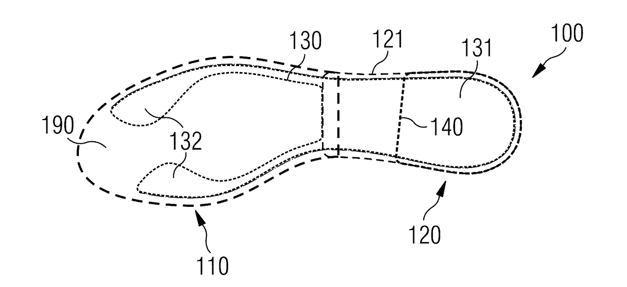
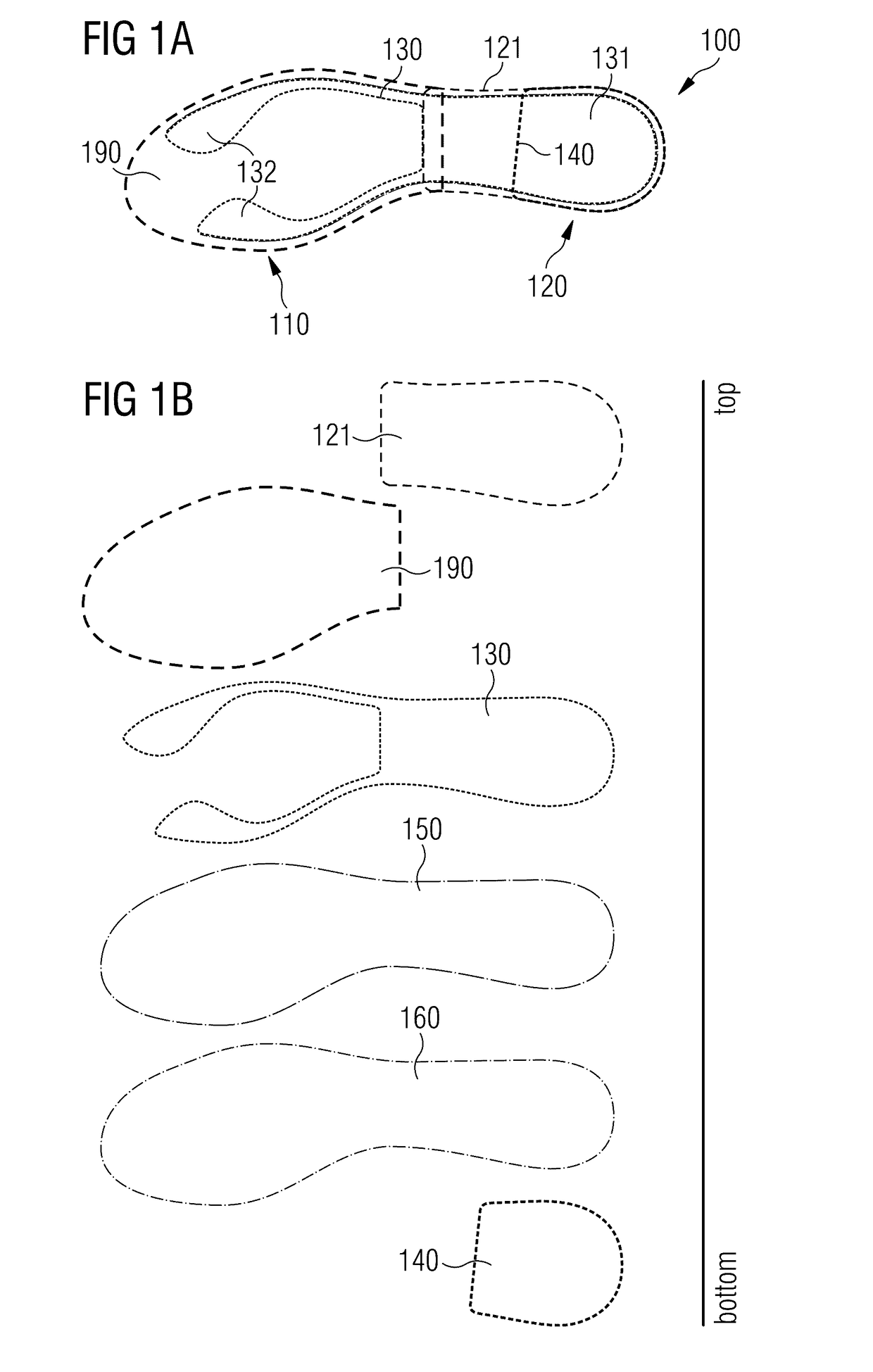
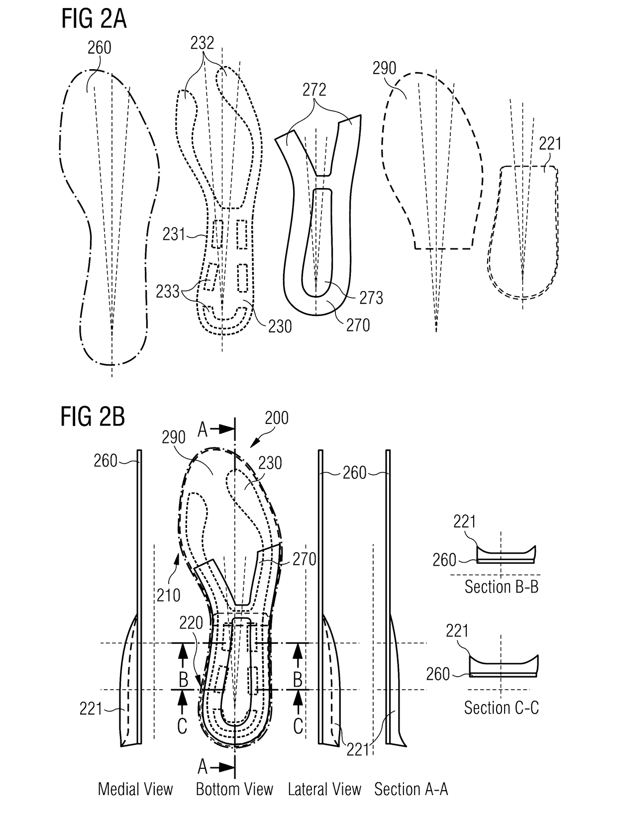
The present invention relates to a sole element, such as an insole, for a shoe, in particular for a sports shoe, as well as to a shoe, in particular a sports shoe. A sole element for a shoe comprises a first portion and a second portion, wherein the second portion comprises a deformable material, which is adapted to generate heat by being deformed. The sole element moreover comprises a transport element adapted for selectively directing the generated heat from the second portion to the first portion.

Description

CROSS-REFERENCE TO RELATED APPLICATIONS[0001]This application claims priority to German application 10 2015 224 702.3, filed Dec. 9, 2015, which is incorporated herein in its entirety by reference thereto.1. TECHNICAL FIELD[0002]The present invention relates to a sole element, such as an insole, for a shoe, in particular for a sports shoe, as well as to a shoe, in particular a sports shoe.2. BACKGROUND[0003]Shoes may provide their wearer with various functionalities such as traction, cushioning, protection from sharp objects, heat management, etc. Therein, different regions of a shoe may be provided with varying properties according to the different needs in these regions.[0004]For example, from document U.S. Pat. No. 6,528,140 it is known that an article of footwear may provide a dual energy management system. For example, a first area in a forefoot portion may comprise an elastic material, whereas a second area in a rearfoot portion comprises a viscous material. Such a design may ...

Claims


Application Information

Patent Timeline
IPC IPC(8): A43B7/02A43B5/00A43B17/14A43B7/34A43B17/00A43B17/02
CPCA43B7/02A43B17/006A43B5/00A43B17/14A43B7/34A43B17/02A43B13/18A43B13/38
Inventor KIRK, ROBERT FRANKKIRUPANANTHAM, GIRIDHARANHOLMES, CHRISTOPHER EDWARDCOONROD, ZACHARY CLINTONKORGER, HARALDLAITENBERGER, PETER GEORG
Owner ADIDAS
Learn More