Optical module and optical transmission device

a technology applied in the field of optical modules and optical transmission devices, to achieve the effect of enhancing a shielding function

Inactive Publication Date: 2017-06-15
LUMENTUM JAPAN INC
View PDF4 Cites 4 Cited by
  • Summary
  • Abstract
  • Description
  • Claims
  • Application Information

AI Technical Summary

Benefits of technology

[0007]It is an object of the invention to enhance a shielding function against electromagnetic interference.
[0008](1) An optical module according to an aspect of the invention is an optical module attachable to and detachable from a cage, including: a module case; a slider attached to the outside of the module case for releasing coming-off prevention from the cage; and a leakage reducing layer intervening between the module case and the slider to reduce leakage of an electromagnetic wave. According to the aspect of the invention, since the electromagnetic wave leaking between the module case and the slider can be reduced by the leakage reducing layer, a shielding function against electromagnetic interference can be enhanced.
[0017](10) An optical transmission device according to another aspect of the invention includes; an optical module; and a cage including a first shield finger provided in contact with the optical module so as to provide electromagnetic shielding, the cage being configured to allow the optical module to be attachable thereto and detachable therefrom, wherein the optical module includes a module case, a slider attached to the outside of the module case for releasing coming-off prevention from the cage, and a leakage reducing layer intervening between the module case and the slider at a position facing the first shield finger to reduce leakage of an electromagnetic wave when the optical module is attached to the cage. According to the aspect of the invention, since the electromagnetic wave leaking between the module case and the slider can be reduced by the leakage reducing layer, a shielding function against electromagnetic interference can be enhanced.

Problems solved by technology

However, when the operating frequency is high, electromagnetic waves pass through the gap between the optical module and the cage even if the gap is small, and the electromagnetic waves are emitted to the outside of a host device.

Method used


Image

  • Optical module and optical transmission device
  • Optical module and optical transmission device
  • Optical module and optical transmission device

Examples


Embodiment Construction

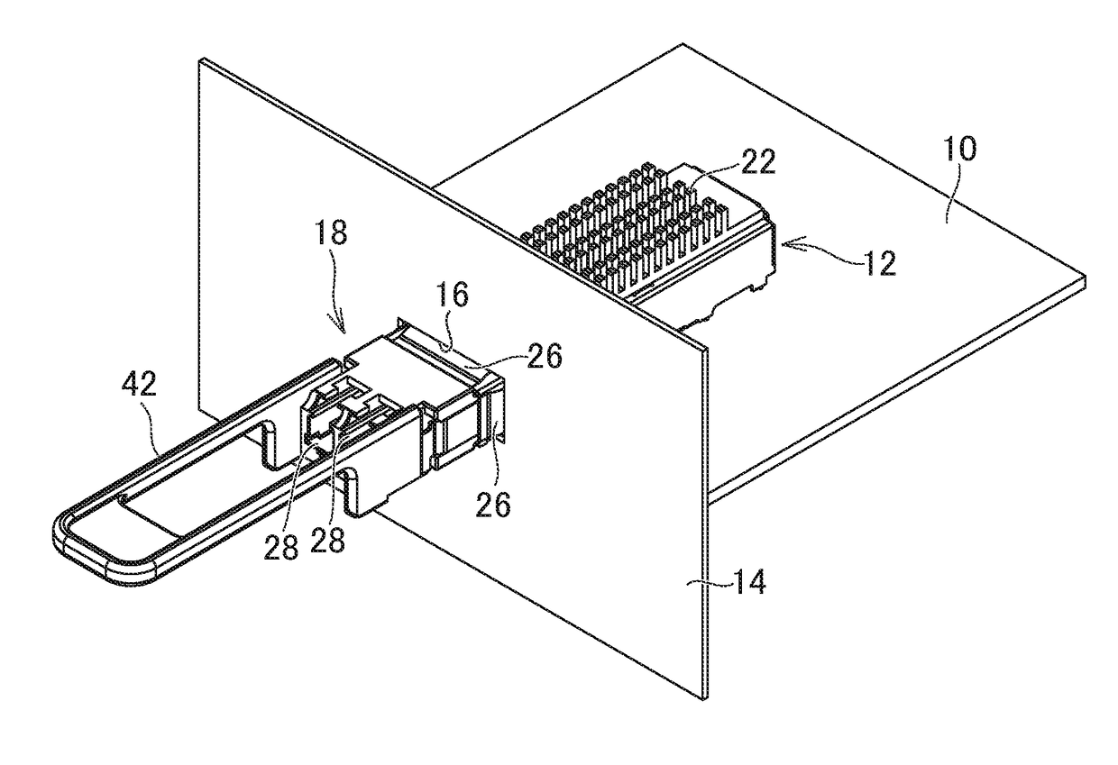
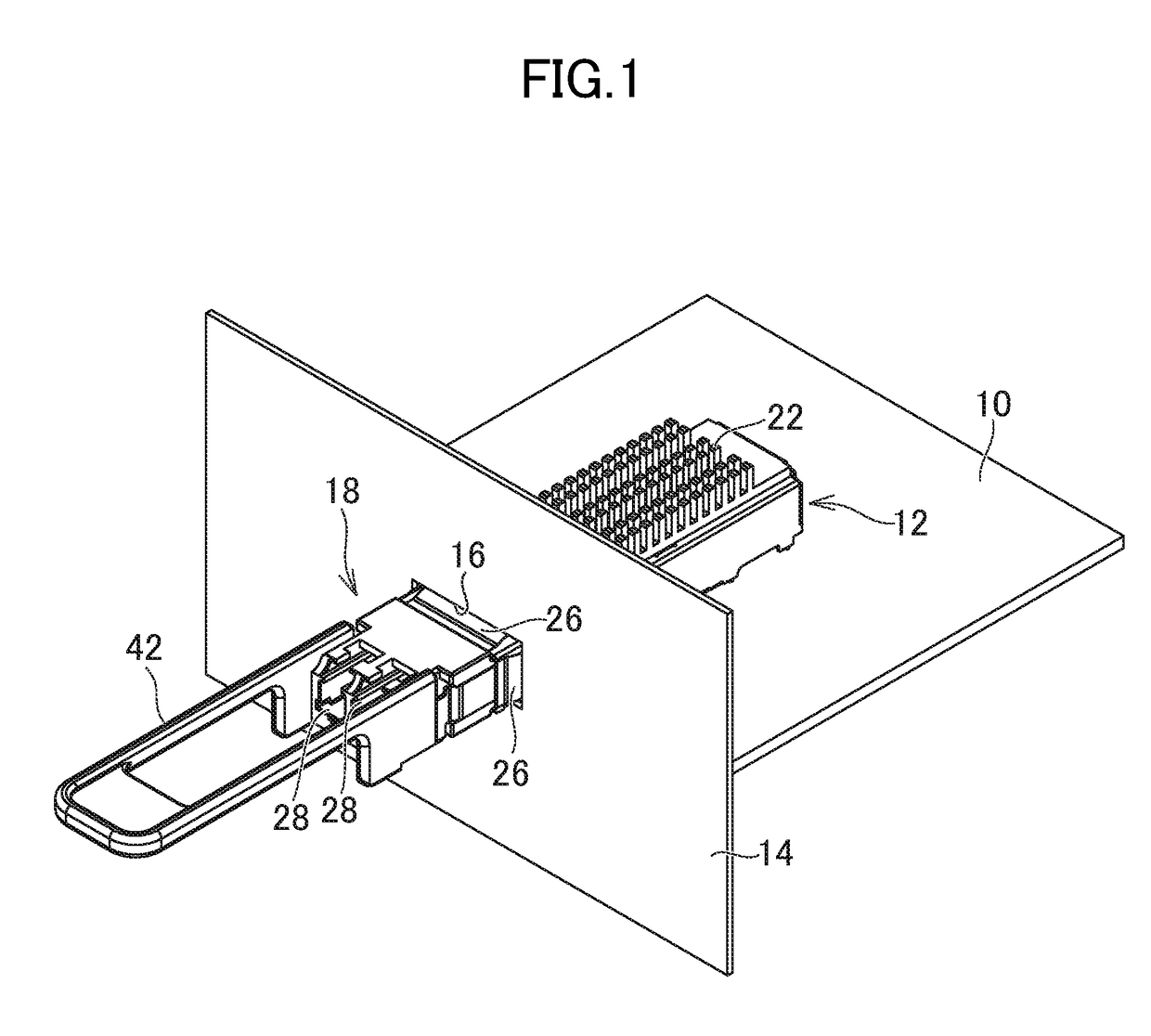
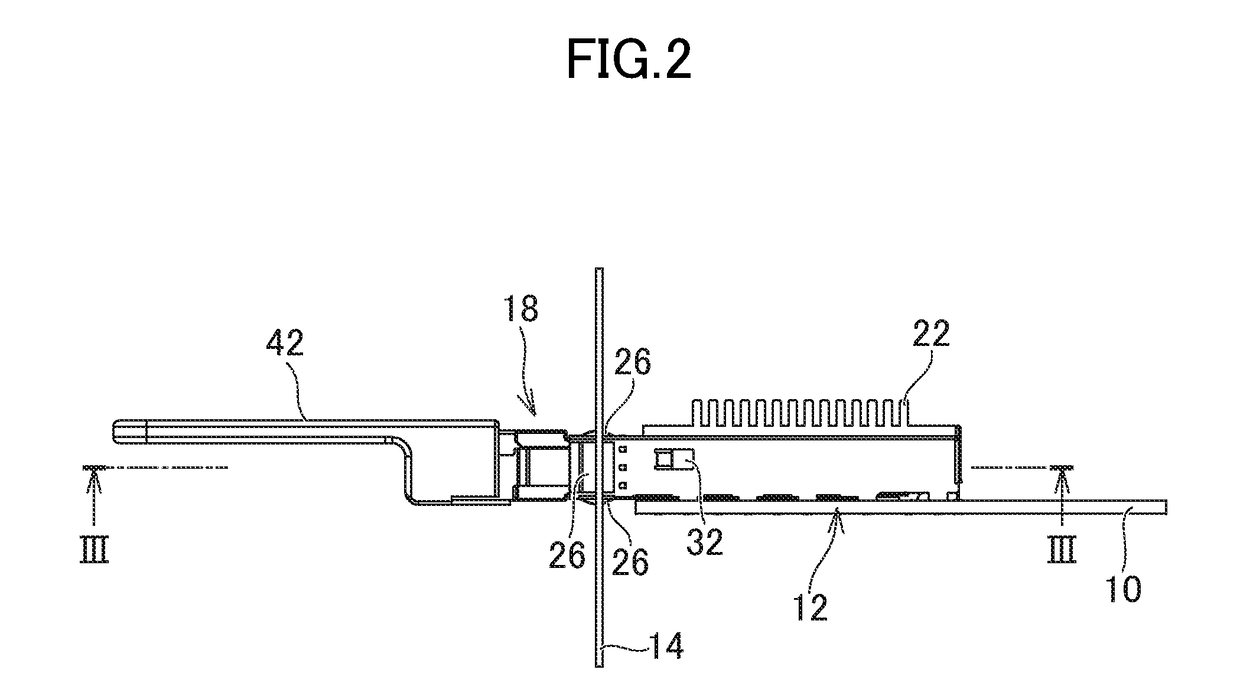
[0033]Hereinafter, an embodiment of the invention will be described with reference to the drawings. FIG. 1 is a perspective view showing a portion of an optical transmission device according to the embodiment of the invention. FIG. 2 is a side view of the optical transmission device shown in FIG. 1. FIG. 3 is a cross-sectional view of the optical transmission device shown in FIG. 2, taken along line III-III.

[0034]The optical transmission device includes a circuit board 10. Many cages 12 are mounted on the circuit board 10, and one of the cages 12 is shown in FIG. 1. The end portion of the cage 12 is inserted through a hole 16 of a front plate 14. The front plate 14 serves as the frame of the cage 12 and thus is also referred to as “bezel”. The cage 12 includes an insertion port 20 (see FIG. 4) for inserting an optical module 18, is hollow, and is configured to allow the optical module 18 to be attachable thereto and detachable therefrom. The cage 12 is made of a conductor such as me...


PUM


Abstract

An optical module is attachable to and detachable from a cage. The optical module includes a module case, a slider attached to the outside of the module case for releasing coming-off prevention from the cage, and a leakage reducing layer intervening between the module case and the slider to reduce leakage of an electromagnetic wave.

Description

CROSS-REFERENCE TO RELATED APPLICATION[0001]The present application claims priority from Japanese applications JP2015-243205 filed on Dec. 14, 2015, and JP2016-166718 filed on Aug. 29, 2016, the contents of which are hereby incorporated by reference into this application.BACKGROUND OF THE INVENTION[0002]1. Field of the Invention[0003]The present invention relates to an optical module and an optical transmission device.[0004]2. Description of the Related Art[0005]As an optical module used in optical fiber communication, an optical module having an attachable and detachable, and pluggable structure for easy replacement due to breakage, performance degradation, or the like has been known (see JP 2008-257235 A and JP 2008-233645 A). Such an optical module is configured to be attachable to and detachable from a cage mounted on a circuit board including an electronic circuit, and coming-off prevention from the cage is achieved with an engaging portion that catches on a claw formed on the ...

Claims


Application Information

Patent Timeline
Patent Type & Authority Applications(United States)
IPC IPC(8): G02B6/42
CPCG02B6/4278G02B6/4206G02B6/4246G02B6/4261G02B6/4277
Inventor MAEDA, FUMIHIDEOMORI, KOICHIUCHIDA, YOSHIKUNISEKINO, YUJITAKEGUCHI, KOJINAGOYA, KAZUTAKAISHII, HIROYOSHI
Owner LUMENTUM JAPAN INC
Why Eureka
Try Eureka