
Transfer apparatus and transfer method

a transfer apparatus and transfer method technology, applied in the field of transfer techniques, can solve the problems of insufficient establishment of a technology capable of responding to such a need, inability to apply the printing technique in some cases, and inability to achieve the effect of preventing local deformation and positional deviation of the second plate body due to non-uniform pressing

Inactive Publication Date: 2017-06-22
DAINIPPON SCREEN MTG CO LTD
View PDF5 Cites 0 Cited by
  • Summary
  • Abstract
  • Description
  • Claims
  • Application Information

AI Technical Summary

Benefits of technology

The invention is a transfer apparatus that allows for stable pressing force between two plate bodies. It includes a roller member that is biased towards the second plate body and positioned to come into contact with its lower surface. The roller member is restrained from displacing beyond its original position, ensuring uniform pressing force in the axial direction. This prevents local deformation and positional deviation of the second plate body due to non-uniform pressing. The transfer method involves arranging the plate bodies in a horizontal posture, bringing the roller member into contact with the second plate body, and causing the roller member to travel in a parallel direction while pressing the second plate body against the first plate body. The invention provides a stable and uniform pressing force between the plate bodies, improving the transfer process.

Problems solved by technology

Thus, it is not appropriate in some cases to simply apply the printing technique as it is.
For these purposes, the conventional technique for adjusting a pressure ex post facto after two objects are brought into contact as described above cannot be necessarily said to be appropriate.
However, there is a problem that a technique capable of responding to such a need has not been sufficiently established yet.

Method used


Image

  • Transfer apparatus and transfer method
  • Transfer apparatus and transfer method
  • Transfer apparatus and transfer method

Examples


Embodiment Construction

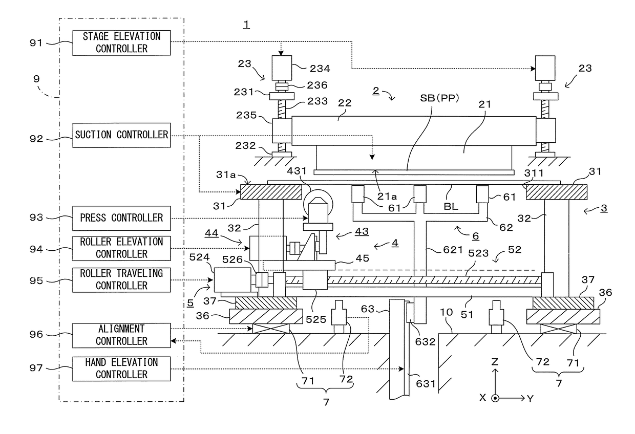
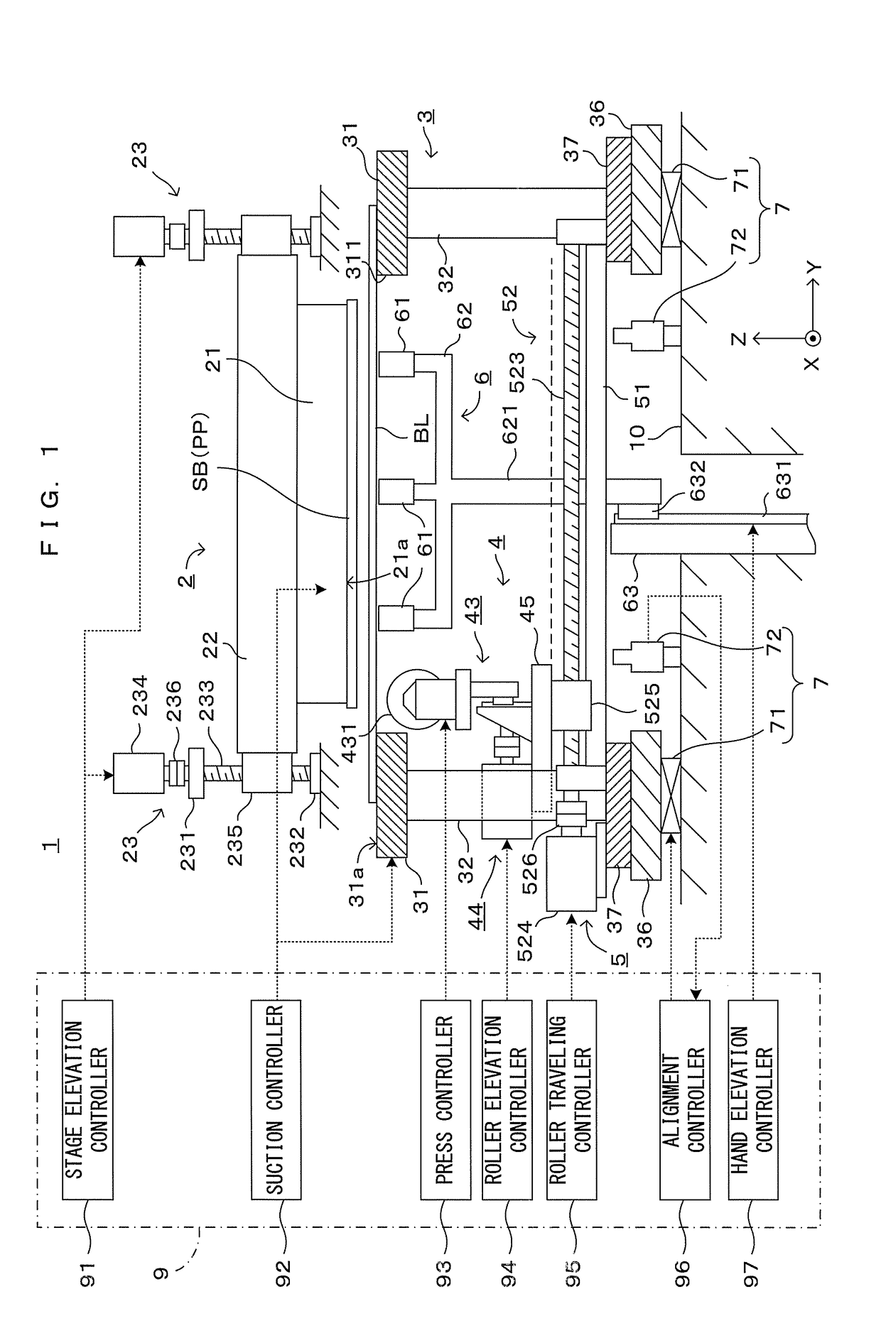
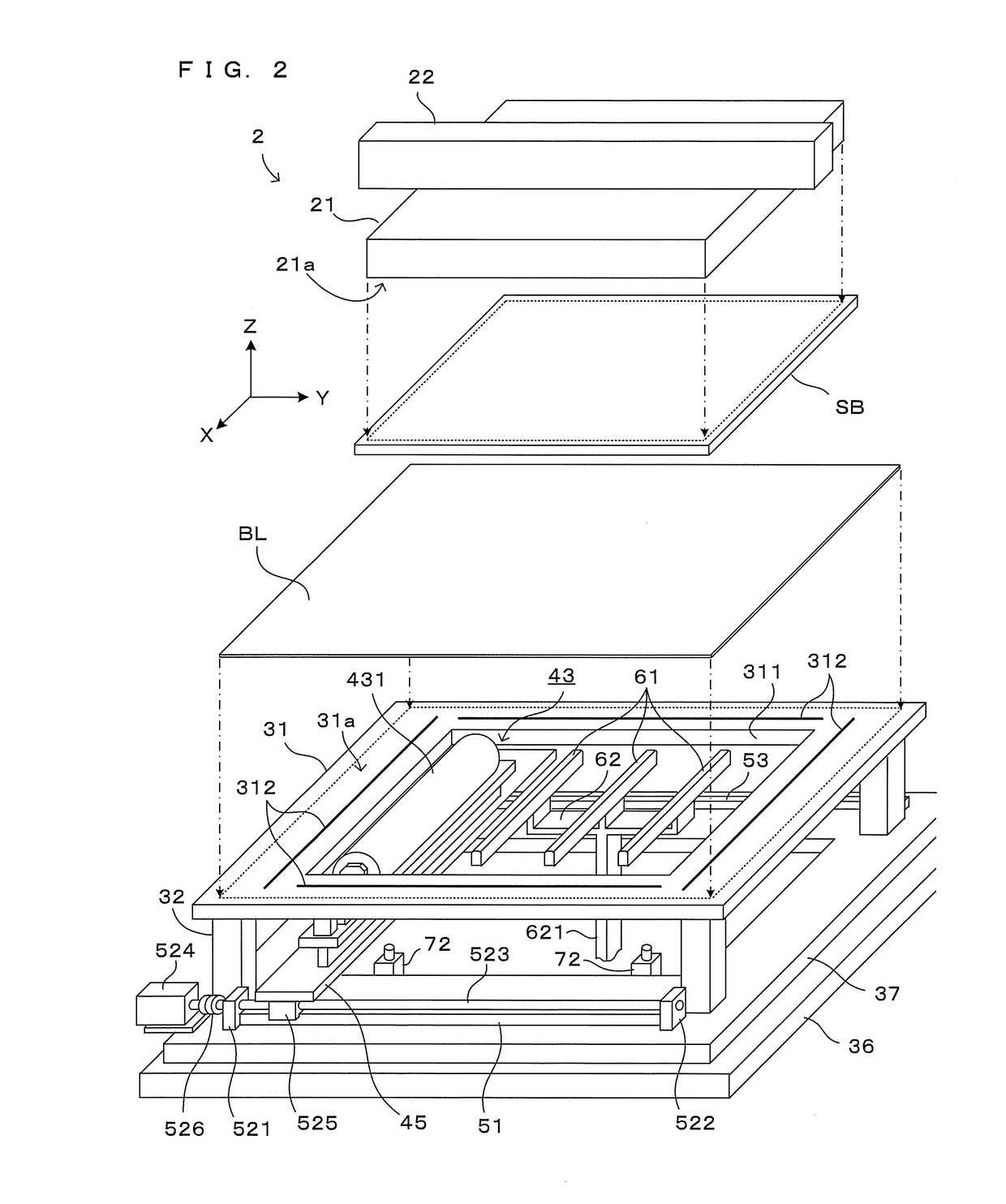
[0034]FIG. 1 is a side view schematically showing one embodiment of a transfer apparatus according to this invention. Further, FIG. 2 is a diagram showing the configuration of a main part of this transfer apparatus. XYZ orthogonal coordinate axes are set as shown in FIG. 1 to comprehensively show directions in each figure. Here, an XY plane represents a horizontal plane. Further, a Z axis represents a vertical axis, more specifically, a (−Z) direction represents a vertically downward direction.

[0035]This transfer apparatus 1 is structured such that an upper stage block 2, a lower stage block 3, a transfer roller block 4, a roller travel driver 5, a supporting hand unit 6 and an alignment unit 7 are arranged on a main frame 10. Further, besides the above, the transfer apparatus 1 includes a control unit 9 for performing a predetermined operation by controlling each component of the apparatus in accordance with a processing program stored in advance.

[0036]First, the overall configurat...


PUM

PropertyMeasurementUnit
heightaaaaaaaaaa
displacementaaaaaaaaaa
biasing forceaaaaaaaaaa

Abstract

It is aimed to provide a technique enabling a roller member to press a plate body with a uniform and stable pressing force. A transfer roller 431 configured to come into contact with a blanket BL and press the blanket BL against a substrate SB is rotatably supported by a pair of supports 430 on opposite end parts thereof. Supporting angles 4334 configured to support a rotary shaft of the transfer roller 431 are supported movably upward and downward by linear guides 4332, 4333 and biased upwardly by biasing portions 434. Displacements of the supporting angles 4334 by biasing forces are restrained at a predetermined height by stoppers 435, and the posture of the transfer roller 431 (inclination of the rotary shaft) when the transfer roller 431 approaches the blanket BL from below is controlled. Restraint by the stoppers 435 is released when the blanket BL is pressed against the substrate SB and a constant pressing force is applied to the blanket BL by the biasing forces.

Description

CROSS REFERENCE TO RELATED APPLICATION[0001]The disclosure of Japanese Patent Application No. 2015-245359 filed on Dec. 16, 2015 including specification, drawings and claims is incorporated herein by reference in its entirety.BACKGROUND OF THE INVENTION[0002]1. Field of the Invention[0003]This invention relates to a transfer technique for transferring an object to be transferred from one plate body to another plate body by bringing two plate bodies into contact.[0004]2. Description of the Related Art[0005]As a technique for forming a pattern or thin film on a plate body such as a glass substrate or semiconductor substrate, a technique for transferring an object to be transferred such as a pattern or thin film carried on a principal surface of one plate body to another plate body by bringing two plate bodies into contact with each other is known. One method of this is to bring two plate bodies into close contact and transfer an object to be transferred by pressing one of the two plat...

Claims


Application Information

Patent Timeline
Patent Type & Authority Applications(United States)
IPC IPC(8): B41F16/00B41F3/00
CPCB41F3/00B41F16/00B32B33/00B41F16/0033B41F16/008B41F16/0053H01L21/67132B41F16/0093B41M5/38221
Inventor KAJINO, ITSUKISHOJI, KAZUHIROMASUICHI, MIKIO
Owner DAINIPPON SCREEN MTG CO LTD
Learn More