Method of manufacturing liquid crystal device and liquid crystal device having a polarization separating element outside a display area

a technology of liquid crystal cell and polarizing plate, which is applied in the direction of lighting and heating apparatus, combustion process, instruments, etc., can solve the problems of display quality deterioration, inability to acquire, and difficulty in accurately adjusting the position of the optical axis of the polarizing plate in relation to the liquid crystal cell

Inactive Publication Date: 2014-04-15
138 EAST LCD ADVANCEMENTS LTD
View PDF13 Cites 1 Cited by
  • Summary
  • Abstract
  • Description
  • Claims
  • Application Information

AI Technical Summary

Benefits of technology

[0009]According to the configuration of Applied Example 1, the liquid crystal device includes the first optical element that is used as the reference for the positional adjustment of the polarizer at the time when the polarizer is to be attached. Accordingly, the optical axis of the polarizer can be optically adjusted to a predetermined position by using the optical axis of the first optical element as the reference, and whereby any relative positional deviation between the liquid crystal cell and the polarizer can be decreased. Therefore, any decrease in the contrast of the liquid crystal device is suppressed, and whereby the display quality of the liquid crystal device can be improved.APPLIED EXAMPLE 2
[0031]According to the configuration of Applied Example 12, the optical axis of the first polarizer is optically adjusted to a predetermined position by using the optical axis of the first optical element as the reference, and whereby the relative positional relationship of the first polarizer with the liquid crystal cell is determined. Accordingly, any relative positional deviation between the liquid crystal cell and the first polarizer can be decreased. Therefore, the deterioration of the optical characteristic such as the contrast of the liquid crystal device is suppressed, and whereby the display quality of the liquid crystal device can be improved. In addition, the positional relationship between one polarizer and the liquid crystal cell is determined and the polarizer is attached to the liquid crystal cell in the same process. Accordingly, an increase in the number of processes for the positional adjustment and the attachment can be suppressed.APPLIED EXAMPLE 13
[0049]According to the configuration of Applied Example 21, even when the first polarizer is arranged on the outer side of any substrate between the first substrate and the second substrate, the first optical element does not overlap with the liquid crystal layer and the second substrate in the plan view. Accordingly, the liquid crystal layer and the second substrate are not interposed between the first optical element and the first polarizer. Thus, when the optical axis of the first polarizer is optically adjusted to a predetermined position by using the optical axis of the first optical element as the reference, the optical influence of the liquid crystal layer and the second substrate is excluded. Accordingly, the position of the first polarizer relative to the liquid crystal cell can be adjusted more accurately.APPLIED EXAMPLE 22
[0057]According to the configuration of Applied Example 25, even when the polarizer does include the polarizing plate and the optical compensation plate, any relative positional deviation among the liquid crystal cell, the first polarizer, and the second polarizer can be decreased.

Problems solved by technology

Accordingly, when there is any deviation in the predetermined arranging positions of the liquid crystal cell and the polarizing plate in a process for attaching the polarizing plates to the liquid crystal cell, the desired optical characteristic (the contrast and the like) cannot be acquired, and whereby the display quality deteriorates.
Thus, when there is a deviation between the outer shape of the polarizing plate and the optical axis, it is difficult to accurately adjust the position of the optical axis of the polarizing plate in respect to the liquid crystal cell.

Method used


Image

  • Method of manufacturing liquid crystal device and liquid crystal device having a polarization separating element outside a display area
  • Method of manufacturing liquid crystal device and liquid crystal device having a polarization separating element outside a display area
  • Method of manufacturing liquid crystal device and liquid crystal device having a polarization separating element outside a display area

Examples


first embodiment

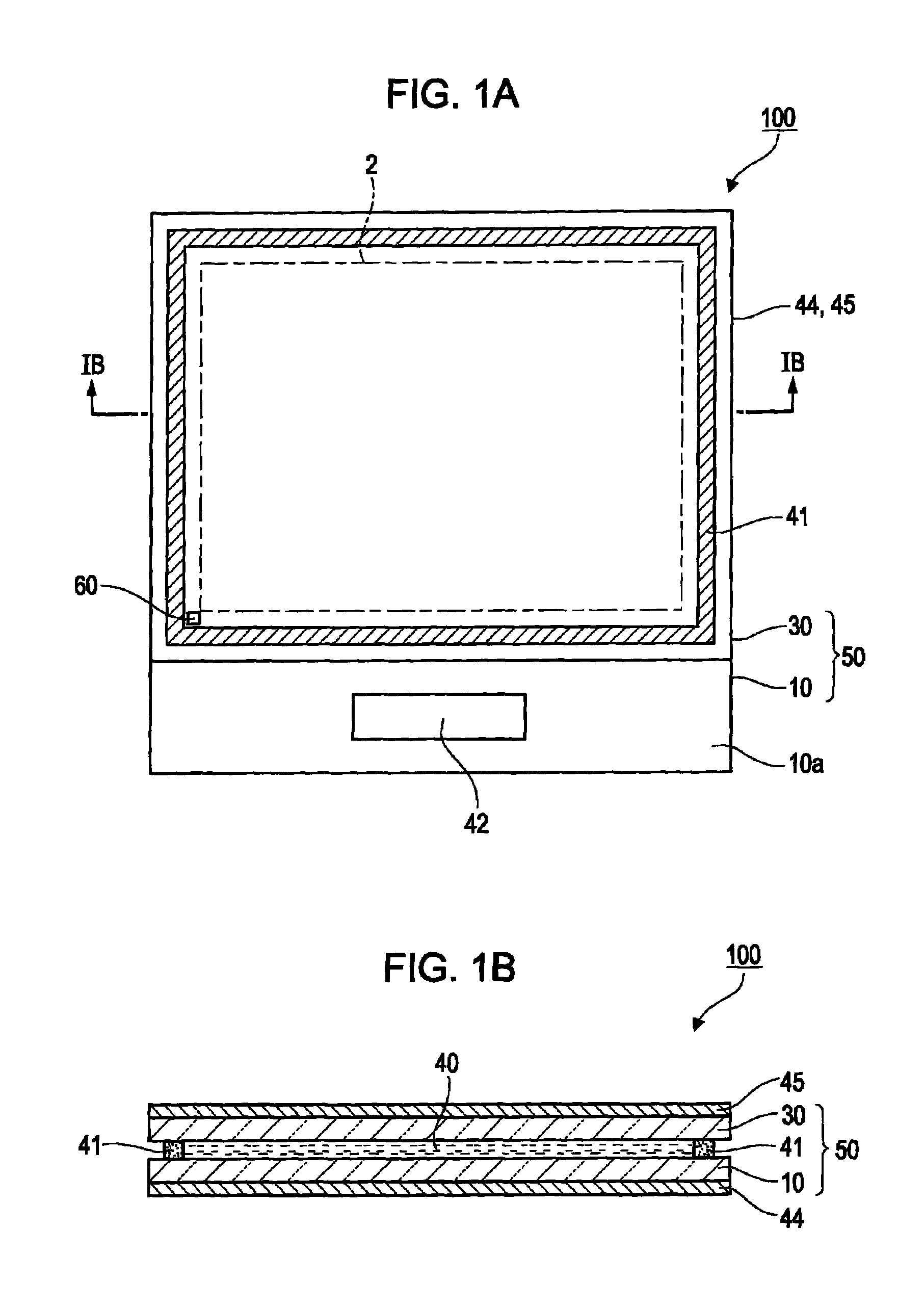
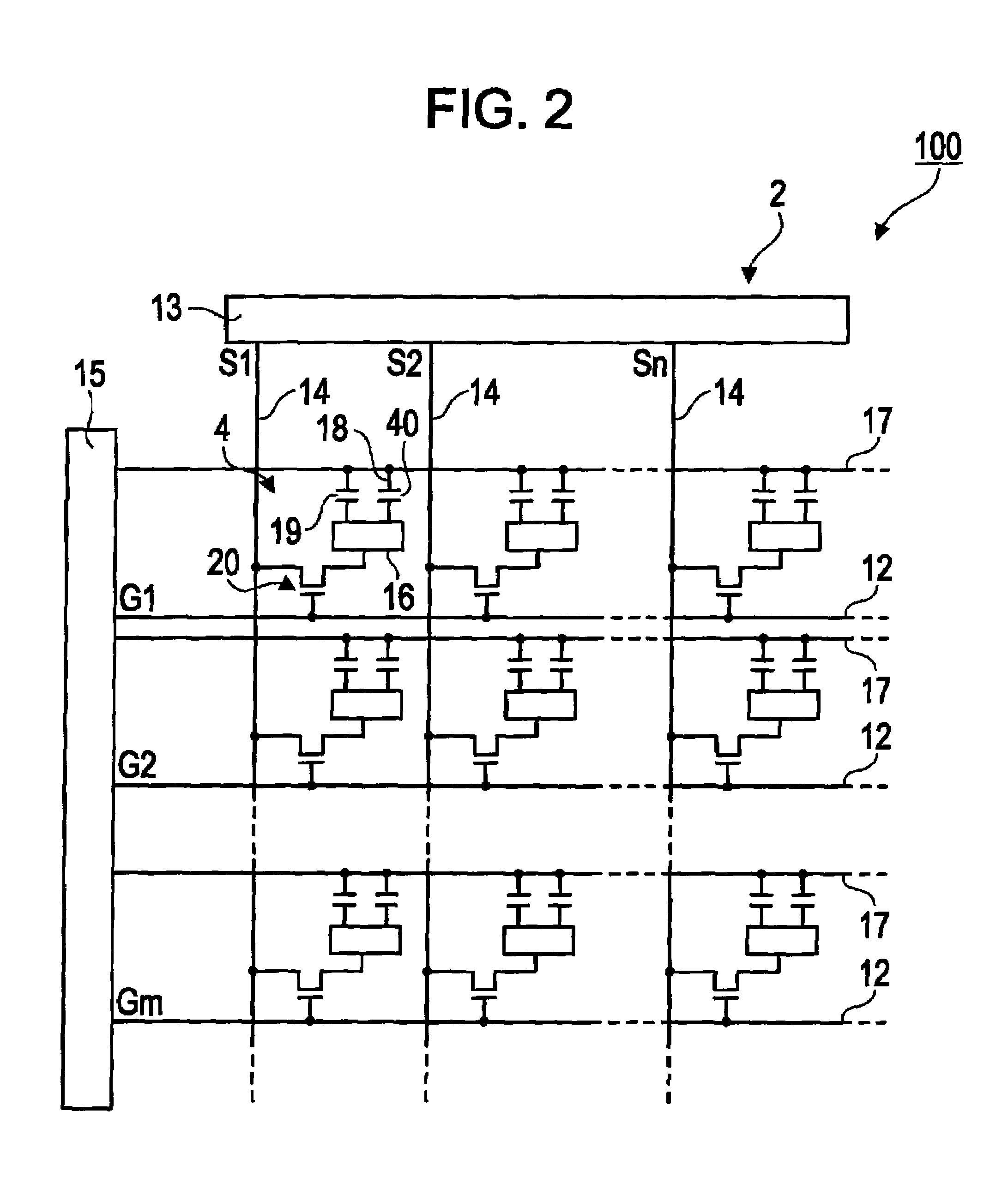
[0077]First, a liquid crystal device according to a first embodiment of the invention will be described with reference to the drawings. FIGS. 1A and 1B are diagrams showing a schematic configuration of the liquid crystal device according to the first embodiment. In particular, FIG. 1A is a plan view of the liquid crystal device, and FIG. 1B is a cross-sectional view taken along line IB-IB shown in FIG. 1A. FIG. 2 is an equivalent circuit diagram showing the electrical configuration of the liquid crystal device according to the first embodiment. FIGS. 3A and 3B are diagrams showing the pixel configuration of the liquid crystal device according to the first embodiment. In particular, FIG. 3A is a plan view showing the pixel configuration for the case where the liquid crystal device is viewed from an opposing substrate side, and FIG. 3B is a diagram showing the aligning direction of a liquid crystal cell. FIG. 4 is a cross-sectional view taken along line IV-IV shown in FIG. 3A. In FIG....

second embodiment

[0144]Next, a liquid crystal device according to a second embodiment of the invention will be described with reference to the drawings. FIGS. 11A and 11B are diagrams showing a wire grid polarizer according to the second embodiment. In particular, FIG. 11A is a perspective view showing a schematic configuration of the wire grid polarizer, and FIG. 11B is a diagram showing the condition of the optical design thereof.

[0145]The directions of the transmission and reflection axes of the wire grid polarizer of the liquid crystal device of the second embodiment are different from those of the liquid crystal device of the first embodiment. However, the other configurations of the second embodiment are the same as those of the first embodiment. To each constituent element that is common to the first embodiment, a same reference sign is attached, and a description thereof is omitted here.

[0146]As shown in FIG. 11A, the wire grid polarizer 62 that is included in the liquid crystal device accor...

third embodiment

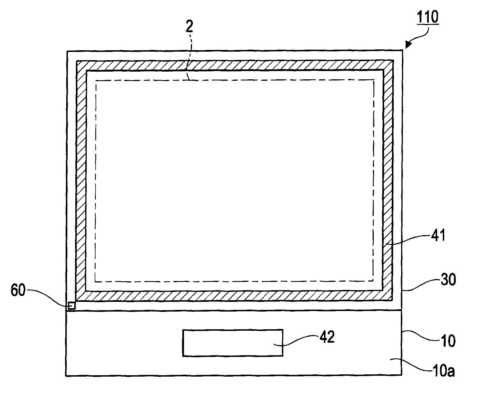
[0155]Next, a liquid crystal device according to a third embodiment of the invention and a method of manufacturing the liquid crystal device will be described with reference to the drawings. FIGS. 12A and 12B are plan views showing a schematic configuration of the liquid crystal device according to the third embodiment.

[0156]A difference between the liquid crystal device according to the third embodiment and the liquid crystal device according to the first embodiment is that the wire grid polarizer is arranged outside an area surrounded by the sealing member 41 in the liquid crystal device of the third embodiment. However, the other configurations of the liquid crystal device according to the third embodiment are the same as those according to the first embodiment. To each constituent element that is common to the first embodiment, a same reference sign is attached, and a description thereof is omitted here.

[0157]In an example of the liquid crystal device 110 shown in FIG. 12A, the ...


PUM

PropertyMeasurementUnit
angleaaaaaaaaaa
angleaaaaaaaaaa
heightaaaaaaaaaa

Abstract

A liquid crystal device includes a first substrate and a second substrate that are arranged so as to face each other, a liquid crystal layer that is pinched between the first substrate and the second substrate, one pair of polarizers that are arranged on both outer sides of the first substrate and the second substrate, a first optical element having a polarization separation function that is disposed in at least one spot of the first substrate, and a display area that contributes to display. The first optical element is arranged outside the display area.

Description

BACKGROUND[0001]1. Technical Field[0002]The present invention relates to a method of manufacturing a liquid crystal device and a liquid crystal device.[0003]2. Related Art[0004]Liquid crystal devices include a liquid crystal cell that is acquired by pinching a liquid crystal layer between one pair of substrates that are arranged so as to oppose each other and one pair of polarizing plates that are arranged on both outer sides of the liquid crystal cell. The liquid crystal devices perform a display by using polarized light. Thus, the liquid crystal devices are set such that a predetermined positional relationship is formed between the aligning direction of liquid crystal molecules of the liquid crystal layer and the optical axis of the pair of polarizing plates. Accordingly, when there is any deviation in the predetermined arranging positions of the liquid crystal cell and the polarizing plate in a process for attaching the polarizing plates to the liquid crystal cell, the desired op...

Claims


Application Information

Patent Timeline
Patent Type & Authority Patents(United States)
IPC IPC(8): G02F1/1335G02F1/13
CPCG02F1/133528G02F2001/133548G02F2001/133638G02F1/133548G02F1/133638
Inventor TSUCHIYA, YUTAKASEKI, TAKUMI
Owner 138 EAST LCD ADVANCEMENTS LTD
Why Eureka
Try Eureka