
Image display apparatus

a technology of image display and display screen, which is applied in the direction of picture reproducers using projection devices, television systems, instruments, etc., can solve the problems of bulky and expensive image display screen, and achieve the effect of suppressing contrast degradation and improving illumination efficiency

Inactive Publication Date: 2009-02-12
SAMSUNG ELECTRONICS CO LTD +1
View PDF23 Cites 3 Cited by
  • Summary
  • Abstract
  • Description
  • Claims
  • Application Information

AI Technical Summary

Benefits of technology

[0008]Exemplary embodiments of the present invention provide an image display apparatus with a slim design and improved illumination efficiency and which is able to suppress degradation of contrast thereby eliminating ghosts.

Problems solved by technology

However, the image display apparatus using the total reflection prism 102 becomes bulky and expensive due to the increased number of lenses in the relay lens system 101 and the high price of the total reflection prism.

Method used


Image

  • Image display apparatus
  • Image display apparatus
  • Image display apparatus

Examples


Embodiment Construction

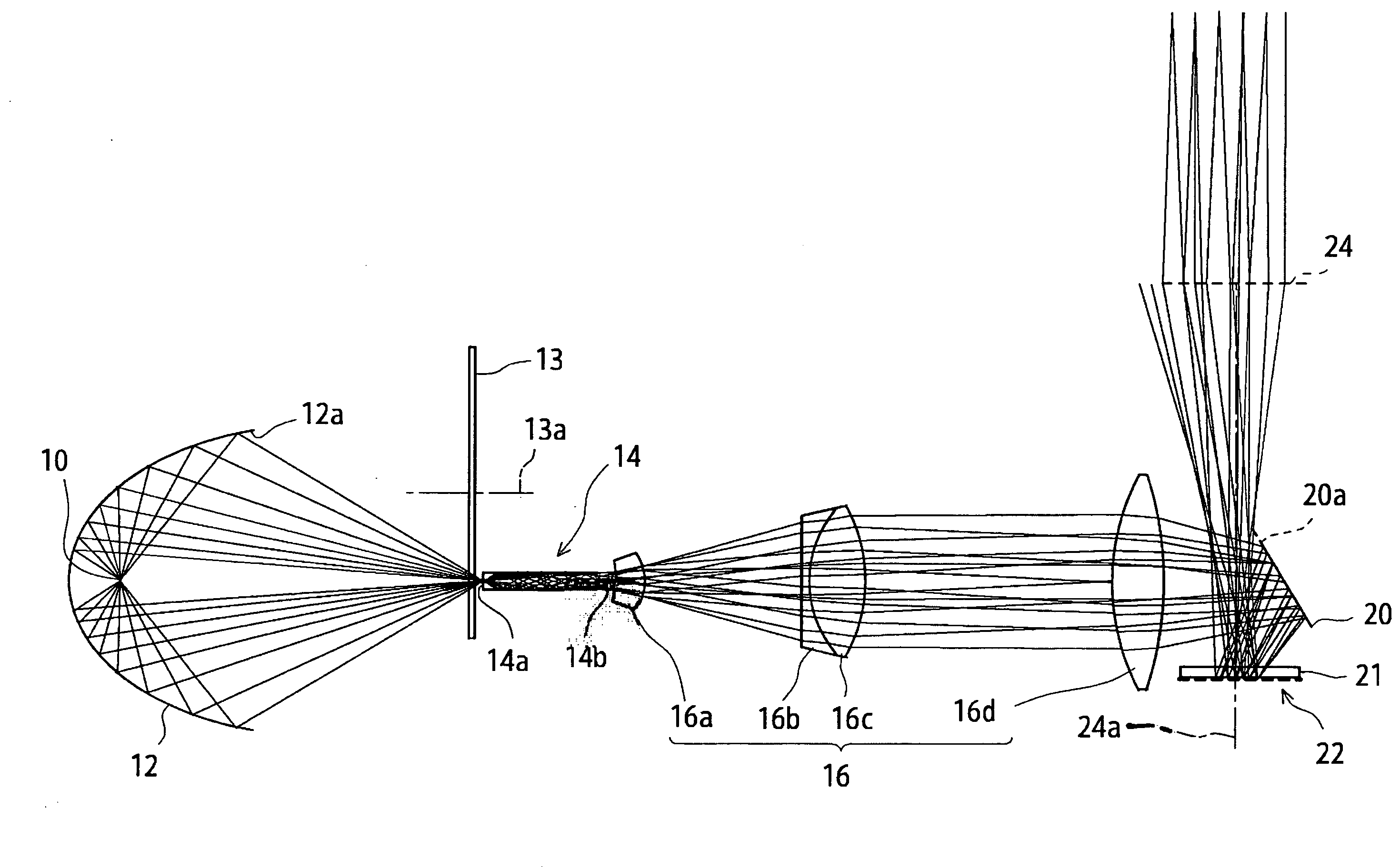
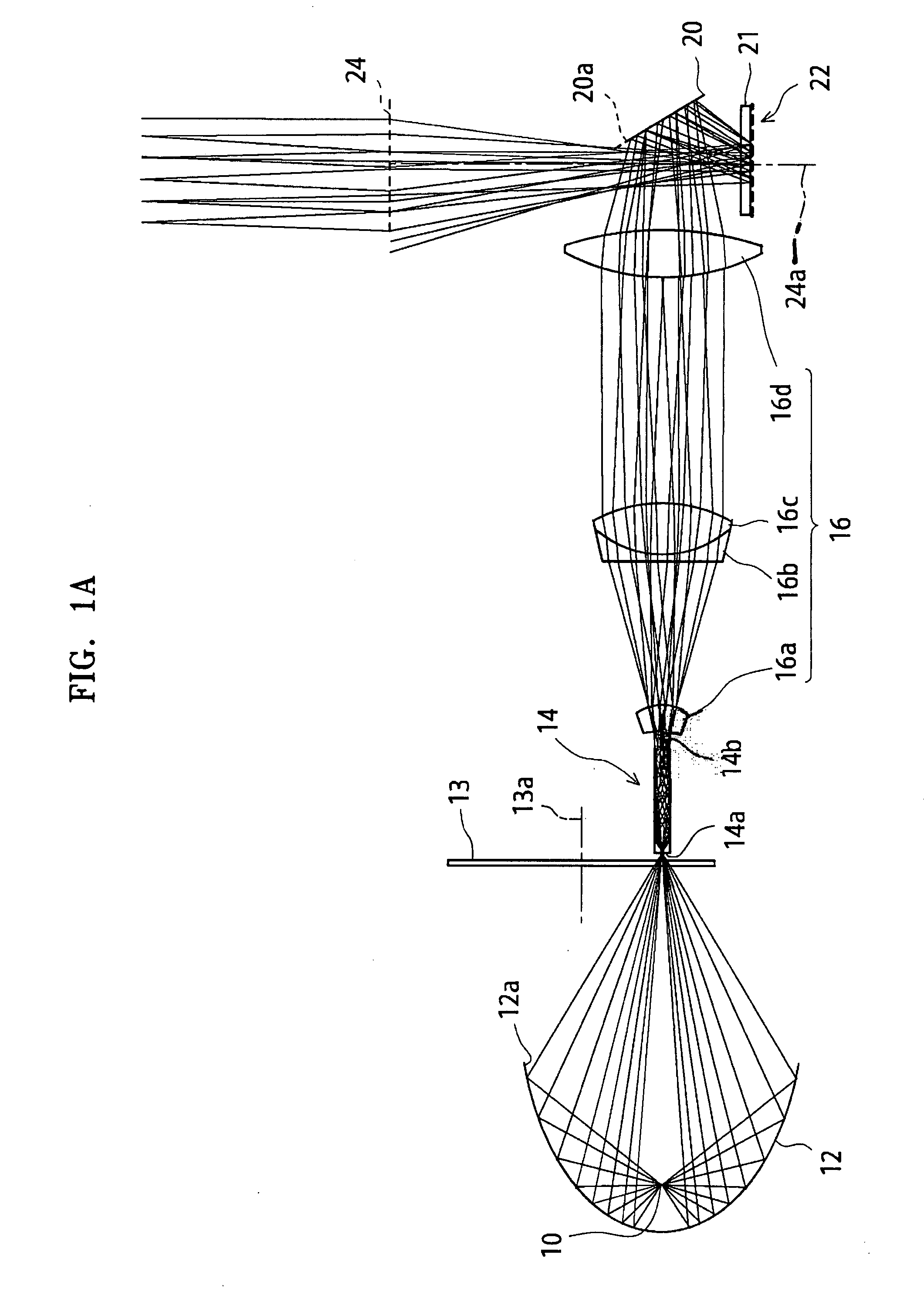
[0027]The present invention will now be described more fully with reference to the accompanying drawings, in which exemplary embodiments of the invention are shown. Referring to FIG. 1A, an image display apparatus according to an exemplary embodiment of the present invention includes a light source 10, a condensing mirror 12, a light tunnel 14, a relay lens system 16, a mirror 20, a reflective display 22, and a projection lens 24.

[0028]The light source 10 is a white light source such as a halogen lamp, a xenon lamp, a metal halide lamp, or a high-pressure mercury lamp. The condensing mirror 12 is disposed to surround the light source 10 and has a beam exit 12a opening toward the light tunnel 14. The condensing mirror 12 reflects and condenses light emitted radially from the light source 10 and exits the light into the light tunnel 14 through the beam exit 12a.

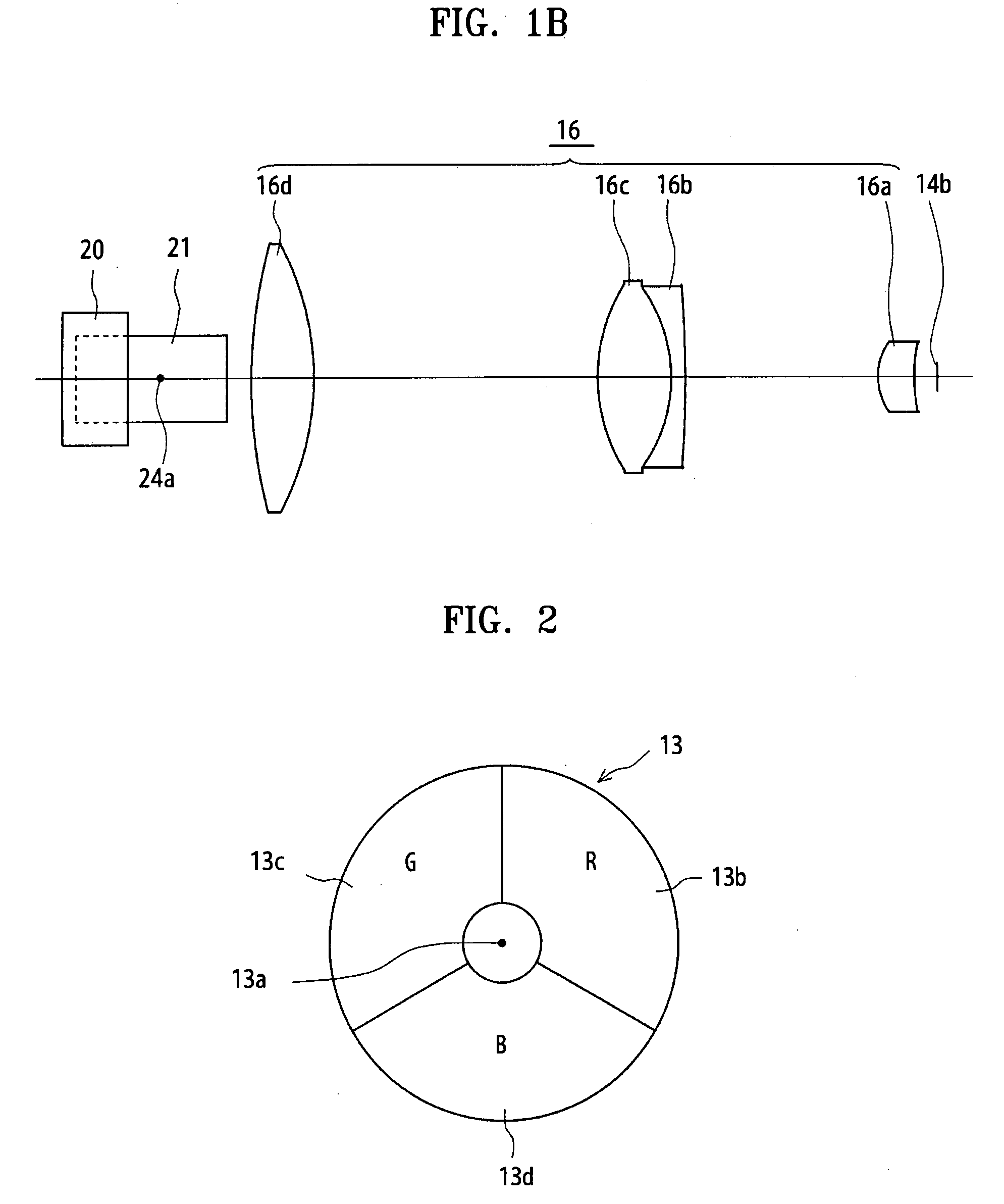
[0029]A widely known color filter 13 is disposed directly in front of an end portion 14a of a light tunnel and sequentially ...


PUM


Abstract

An image display apparatus is provided with a slim design and improved illumination efficiency and which is able to suppress degradation of contrast thereby eliminating ghosts. The image display apparatus includes: a light source; a condensing mirror which condenses light emitted from the light source and makes a virtual secondary light source; a light tunnel on which light passing through a color filter is incident; a relay lens system through which light exiting the light tunnel passes; a first mirror on which the light passing through the relay lens is directly or indirectly incident; a reflective display including a plurality of micromirrors arranged on a substrate in a matrix, on which the light reflected off the mirror is incident, wherein each micromirror is turned ON or OFF by individually changing the slope of the micromirrors and thus angles of reflection; and a projection lens which enlarges and projects light reflected from the micromirrors in the ON state, wherein the relay lens system and the first mirror are disposed opposite to each other with an optical axis of the projection lens interposed therebetween.

Description

CROSS-REFERENCE TO RELATED PATENT APPLICATIONS[0001]This application claims priority from Japanese Patent Application Nos. 10-2004-0216340 and 10-2005-0195004, filed on Jul. 23, 2004, and Jul. 4, 2005, respectively, in the Japanese Intellectual Property Office, the disclosures of which are incorporated herein in their entirety by reference.BACKGROUND OF THE INVENTION[0002]1. Field of the Invention[0003]The present invention relates to an image display apparatus with a plurality of micromirrors that are arranged in a matrix and can change angles of reflection.[0004]2. Description of the Related Art[0005]An example of an image display apparatus employing micromirrors that can turn on or off (reflect or not reflect light into a projection lens) by individually changing the slope of each micromirror, i.e., angles of reflection is conventionally disclosed in Japanese Laid-open Patent Application No. 1996-0014691.[0006]In the image display apparatus configured as shown in FIG. 8, light em...

Claims


Application Information

Patent Timeline
IPC IPC(8): H04N9/31H04N5/74
CPCH04N9/3114H04N9/3197H04N9/3152H04N9/315G02B13/0095G02B26/0833
Inventor YOSHIDA, KAZUSHI
Owner SAMSUNG ELECTRONICS CO LTD
Learn More