Light guide plate, planar light source apparatus, display apparatus, and electronic device

a light guide and display device technology, applied in the direction of lighting and heating devices, planar/plate-like light guides, instruments, etc., can solve the problem of non-uniformity of brightness in liquid crystal display devices, and achieve the effect of suppressing the non-uniformity of brightness in an area and suppressing the decline of contrast between areas

Active Publication Date: 2021-02-11
NICHIA CORP
View PDF0 Cites 2 Cited by
  • Summary
  • Abstract
  • Description
  • Claims
  • Application Information

AI Technical Summary

Benefits of technology

[0021]According to the present invention, it is possible to provide a technique for suppressing brightness non-uniformity of an area illuminated by a light source and also suppressing a decline in contrast between areas caused by incidence of a luminous flux of the area to another area.

Problems solved by technology

In the case of a direct-type backlight, while a plurality of LEDs are arranged directly underneath a liquid crystal display apparatus, brightness non-uniformity easily occurs in the liquid crystal display apparatus between portions directly above the LEDs and other portions.

Method used


Image

  • Light guide plate, planar light source apparatus, display apparatus, and electronic device
  • Light guide plate, planar light source apparatus, display apparatus, and electronic device
  • Light guide plate, planar light source apparatus, display apparatus, and electronic device

Examples


first specific example

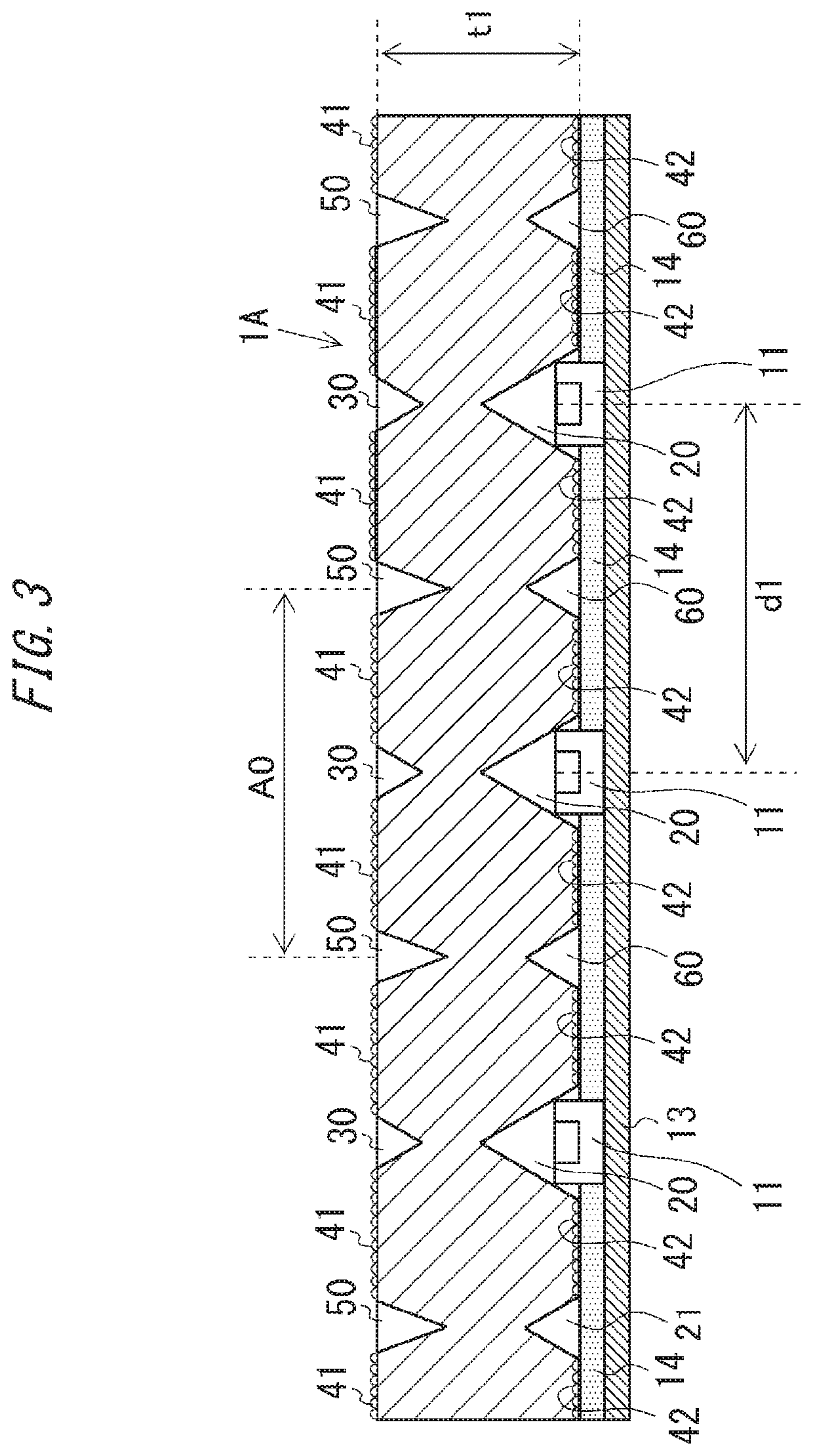
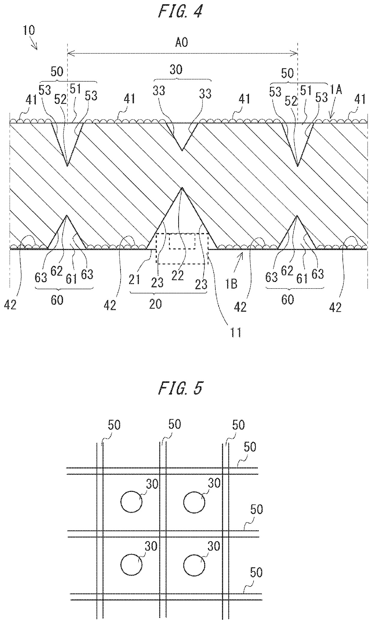
[0052]FIG. 3 is a sectional view of the light guide plate 10. A ratio of sizes of the respective components and the like are not limited to the illustrated example. The light guide plate 10 has a plurality of depressed portions 20 on the lower surface of the light guide plate 10. The depressed portion 20 has a conical shape. The plurality of light sources 11 are arranged on the mounting substrate 13 and one light source 11 is housed inside each depressed portion 20. Light emitted from the light source 11 is incident into the light guide plate 10. Due to light incident into the light guide plate 10 being refracted, reflected, and diffused inside the light guide plate 10 and emitted from a light exit surface 1A of the light guide plate 10, the light exit surface 1A of the light guide plate 10 is uniformly lighted. While a thickness (height) t1 of the light guide plate 10 is, for example, 0.35 mm, the thickness (height) t1 is not limited to this value and may assume another value such ...

second specific example

[0065]FIG. 8 is a sectional view schematically showing a second specific example of the light guide plate 10. In the present specific example, components corresponding to the configuration described above will be assigned corresponding reference numerals and a description thereof will be omitted.

[0066]The light guide plate 10 according to the present specific example is configured so as to be formed by an individual piece for each light source 11 and arranged in a matrix pattern corresponding to the light sources 11.

[0067]The first restricting portion according to the present second specific example is constituted by a side surface 71 of the light guide plate 10 formed as an individual piece. For example, by installing individual pieces of the light guide plate 10 in a row while providing minute gaps between the side surfaces 71 and reflecting light incident to the side surface 71 at angles exceeding the critical angle, traveling, toward the side of the light exit surface outside th...

third specific example

[0072]FIG. 9 is a sectional view schematically showing a third specific example of the light guide plate 10. In the present third specific example, components corresponding to the configurations described above will be assigned corresponding reference numerals and a description thereof will be omitted.

[0073]As shown in FIG. 9, in the present third specific example, a reflective layer 81 is formed on an inner surface of the groove portion 60. By forming a reflective surface on the inclined surface 63 of the groove portion 60 in this manner, light traveling from the inside toward the outside of the illuminated area A0 is reflected toward the inside of the illuminated area A0 when striking the groove portion 60. This configuration restricts traveling, toward the side of the light exit surface outside of the illuminated area A0, of light traveling from the inside toward the outside of the illuminated area A0.

[0074]In addition, FIG. 10 is a diagram showing a modification of the light gui...


PUM

PropertyMeasurementUnit
heightaaaaaaaaaa
thicknessaaaaaaaaaa
luminous fluxaaaaaaaaaa

Abstract

To provide a technique for suppressing brightness non-uniformity of an area illuminated by a light source and also suppressing a decline in contrast between areas caused by incidence of a luminous flux of the area to another area. Provided is a light guide plate including: a diverging portion which is provided on an opposite side of a light exit surface from which light is emitted, the diverging portion causing a luminous flux emitted from a light emitting element to diverge; and a restricting portion which is provided, when a prescribed range from the light emitting element on the light exit surface is defined as an illuminated area illuminated by the light emitting element, in at least a periphery of the illuminated area on the light exit surface and which deflects or shields light traveling from inside toward outside of the illuminated area to restrict traveling, toward a side of the light exit surface, of light traveling toward the outside of the illuminated area.

Description

TECHNICAL FIELD[0001]The present invention relates to a light guide plate, a planar light source apparatus, a display apparatus, and an electronic device.BACKGROUND ART[0002]Backlight systems for liquid crystal display apparatuses include a system referred to as an edge light-type backlight and a system referred to as a direct-type backlight. Direct-type backlights which feature high light utilization efficiency and which enable higher brightness to be readily achieved are used in displays of large-size liquid crystal display apparatuses. In addition, for example, an LED (Light Emitting Diode) which emits white light is used as a light source of a backlight. In the case of a direct-type backlight, while a plurality of LEDs are arranged directly underneath a liquid crystal display apparatus, brightness non-uniformity easily occurs in the liquid crystal display apparatus between portions directly above the LEDs and other portions.[0003]Conventionally, a planar light source apparatus h...

Claims


Application Information

Patent Timeline
Patent Type & Authority Applications(United States)
IPC IPC(8): F21V8/00G02F1/01G02F1/13357
CPCG02B6/0025G02B6/0016G02F1/133606G02F1/0107G02F1/133603G02B6/0031G02B6/0011G02F1/133524G02F1/133608F21S2/00G02F1/133607G02F1/1335G02B6/005
Inventor WATANABE, SHOTAROISHIMI, NAOKIITO, YOSHINORISHIMODA, TOMOKAZU
Owner NICHIA CORP
Why Eureka
Try Eureka