Illumination device for vehicle

Active Publication Date: 2019-03-07
TOYOTA JIDOSHA KK +1
View PDF8 Cites 2 Cited by
  • Summary
  • Abstract
  • Description
  • Claims
  • Application Information

AI Technical Summary

Benefits of technology

[0024]In accordance with the third aspect, a decrease in the contrast at the edge portions of the both end portions sides of the region onto which light is illuminated can be suppressed.
[0025]In accordance with the inventions relating to the fourth and fifth aspects, a decrease in the contrast at the edge portions of the region onto which light is illuminated can be suppressed more.
[0026]I

Problems solved by technology

However, in a structure that changes the direction of illuminated light by controlling a swivel motor, it is difficult to illuminate the light accurately toward a desired region due to wobbling or the like at the time when the swivel motor is operated.
Further, if only illuminating light

Method used


Image

  • Illumination device for vehicle
  • Illumination device for vehicle
  • Illumination device for vehicle

Examples


first embodiment

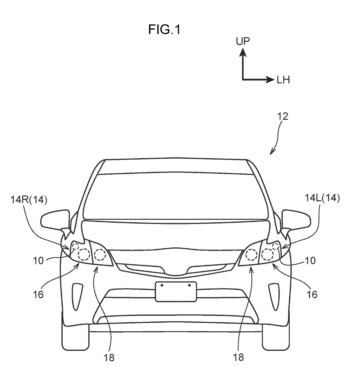
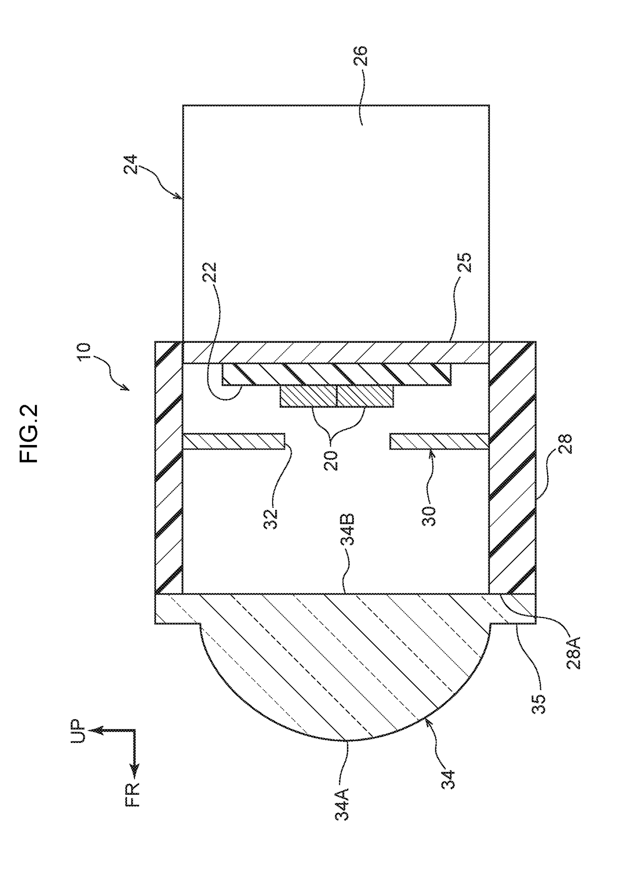
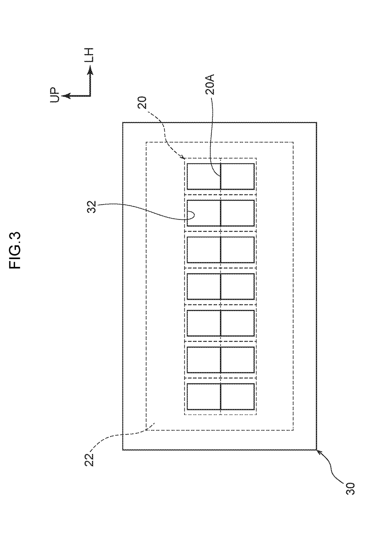
[0053]First, the illumination device 10 for a vehicle relating to the first embodiment is described. As shown in FIG. 2, the illumination device 10 for a vehicle has plural light sources 20 that illuminate light (visible light), a light-blocking member 30 having opening portions 32 on which the light illuminated from the respective light sources 20 is incident, and a projecting lens 34 that emits the light, that has passed through the opening portions 32 of the light-blocking member 30 and is incident on the projecting lens 34, toward an object (as an example, a pedestrian walking on the shoulder or an automobile traveling on the shoulder or the like, that there is the concern that the vehicle 12 may collide with, hereinafter called “pedestrian P”, see FIG. 5).

[0054]The light sources 20 are high-intensity light sources such as light-emitting diodes (LEDs) or the like, and are provided so as to be lined-up in two lines on a substrate 22 that is electrically connected to a control sec...

second embodiment

[0072]The illumination device 10 for a vehicle relating to the second embodiment is described next. Note that regions that are equivalent to those of the above-described first embodiment are denoted by the same reference numerals, and detailed description thereof (including description of common operation) is omitted as appropriate.

[0073]As shown in FIG. 6, in the illumination device 10 for a vehicle relating to the second embodiment, only the shape of the opening portions 32 at the light-blocking member 30 differs from the first embodiment. Namely, the opening portions 32 of this light-blocking member 30 are formed in upside-down T-shapes that are the same height as that of the two upper / lower light sources 20 and that face the light sources 20 in the optical axis direction. When the opening portions 32 of the light-blocking member 30 are made to be such a shape, as shown in FIG. 7, the light that is transmitted through the projecting lens 34 is turned upside-down, and therefore, b...

third embodiment

[0075]The illumination device 10 for a vehicle relating to the third embodiment is described next. Note that regions that are equivalent to those of the above-described first embodiment and second embodiment are denoted by the same reference numerals, and detailed description thereof (including description of common operation) is omitted as appropriate.

[0076]As shown in FIG. 8, in the illumination device 10 for a vehicle relating to the third embodiment, only the shape of the opening portion 32 at the light-blocking member 30 differs from the first embodiment and the second embodiment. Namely, the opening portion 32 of this light-blocking member 30 is a shape in which the upside-down T-shaped opening portions 32 of the second embodiment are continuous in the vehicle transverse direction.

[0077]In other words, at the opening portion 32 of this light-blocking member 30, a lower portion opening 32A which is rectangular and whose length direction is the vehicle transverse direction (the ...


PUM


Abstract

An illumination device for a vehicle includes: plural light sources that are disposed so as to be lined-up in at least one line, and that illuminate light; a light-blocking member having an opening portion onto which light illuminated from the light sources is incident; and a projecting lens that emits, toward an object, light that has passed through the opening portion of the light-blocking member and has been incident on the projecting lens.

Description

CROSS-REFERENCE TO RELATED APPLICATION[0001]This application is based on and claims priority under 35 USC 119 from Japanese Patent Application No. 2017-169879 filed on Sep. 4, 2017, the disclosure of which is incorporated by reference herein.TECHNICAL FIELD[0002]The present disclosure relates to an illumination device for a vehicle.RELATED ART[0003]There has conventionally been proposed a mechanism in which, at the time of traveling on a curved road, by controlling a swivel motor that is interlocked with the turning angle, the illuminated light that is illuminated from the headlights is directed toward the side toward which the vehicle is starting to turn, so as to urge the driver to be cautious (see, for example, Japanese Patent Application Laid-Open (JP-A) No. 6-12901 (Patent Document 1)). Further, there also has conventionally been proposed a device in which the light source of a front headlight is structured by LEDs that are disposed in the form of a two-dimensional matrix, and,...

Claims


Application Information

Patent Timeline
IPC IPC(8): B60Q1/04F21S41/29F21S41/43F21S41/47F21S41/143F21S41/25F21S41/60
CPCB60Q1/04F21S41/295F21S41/43F21S41/47F21S41/143F21S41/25F21S41/60F21Y2115/10B60Q2300/30B60Q2300/40F21S41/10F21W2107/10B60Q1/0035B60Q1/0041B60Q1/143B60Q1/18B60Q2300/45F21S41/285F21S41/255F21S41/663
Inventor MOURI, FUMIHIKOKITAZONO, TAKUYAMYOJIN, NORIKATSU
Owner TOYOTA JIDOSHA KK
Why Eureka
Try Eureka