Bicycle rear derailleur

a rear derailleur and bicycle technology, applied in the direction of chain/belt transmission, vehicle components, vehicle transmission, etc., can solve the problems of chain being too loose to stably mesh with the sprocket, unintentionally switching from one sprocket to another, and chain being shaken, etc., to achieve the effect of enhancing the safety of cycling

Active Publication Date: 2017-06-22
LEE CHI ENTERPRISES +1
View PDF0 Cites 12 Cited by
  • Summary
  • Abstract
  • Description
  • Claims
  • Application Information

AI Technical Summary

Benefits of technology

[0005]In view of the above, the primary objective of the present invention is to provide a bicy...

Problems solved by technology

However, while moving on a rough road surface with bumps or potholes, the chain may be shaken due to the bump or sudden vibration, and thus pull the chain guide to rotate counterclockwise.
In such conditions, the tension of the chain would be reduced, which makes the c...

Method used


Image

  • Bicycle rear derailleur
  • Bicycle rear derailleur
  • Bicycle rear derailleur

Examples


Embodiment Construction

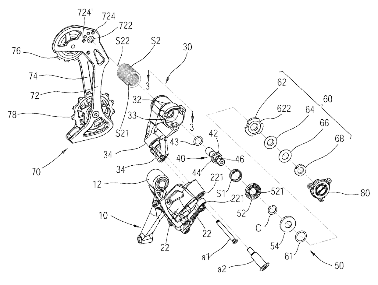
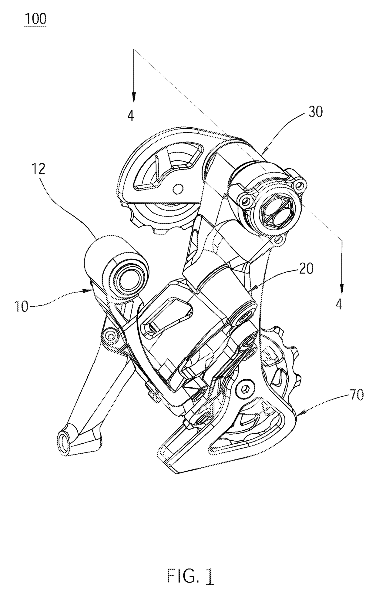
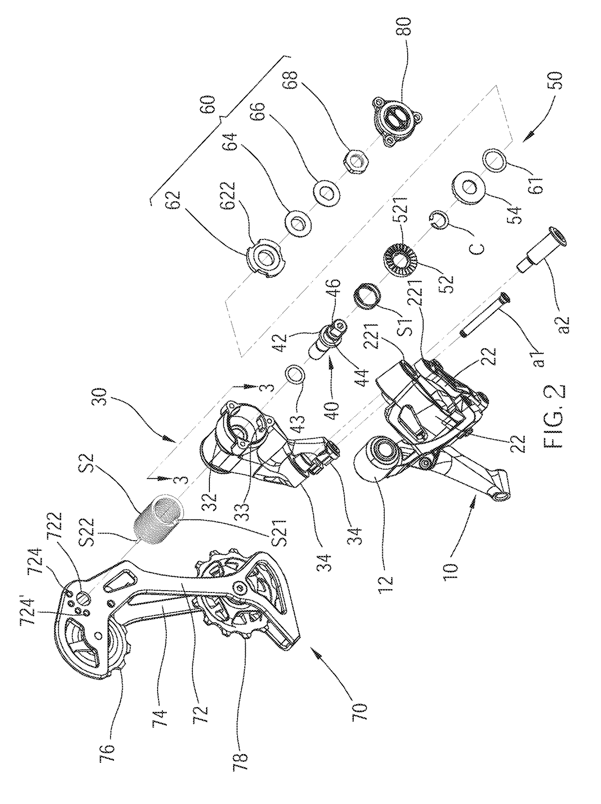
[0017]As shown in FIG. 1 and FIG. 2, a bicycle rear derailleur 100, the first embodiment of the present invention, includes a parallel linkage mechanism which includes a base 10, a linkage assembly 20, and a movable member 30. The bicycle rear derailleur 100 further includes a pivot shaft 40, a restriction assembly 50, a friction assembly 60, and a chain guide 70.

[0018]The base 10 has a mounting portion 12 which is fixed to the rear of a bicycle frame by fasteners such as screws or bolts, and near a side of the sprockets. Additionally, the base 10 can be used as a fixed link of the parallel linkage mechanism.

[0019]The linkage assembly 20 includes two connecting rods 22, wherein each of the connecting rods 22 has an end pivotally connected to the base 10, and another end thereof has a pivot hole 221.

[0020]The movable member 30 includes a main body 32 and two pivot portions 34 connected to the main body 32. As shown in FIG. 2 and FIG. 3, the main body 32 has a chamber 320 therein, and...


PUM


Abstract

A bicycle rear derailleur is provided, which includes a base adapted to be mounted on a bicycle frame, a movable member, a linkage assembly pivotally connected to and between the base and the movable member, a pivot shaft provided within and pivotally rotatable relative to the movable member, a chain guide fixed to an end of the pivot shaft, a restriction assembly provided on the pivot shaft, and a friction assembly provided within the movable member to provide a rotational friction on the restriction assembly. Whereby, the chain guide is pivotally awing toward a first direction by a force; when the chain guide swings toward a second direction which is opposite to the first direction by another force, it is forced by a swing resistance.

Description

BACKGROUND OF THE INVENTION1. Technical Field[0001]The present invention relates generally to a bicycle rear derailleur, and more particularly to a bicycle rear derailleur capable of stabilizing the tension of the chain.2. Description of Related Art[0002]In general, a bicycle rear derailleur mainly includes a base, a movable member, and a chain guide. The base is mounted on the rear of a bicycle frame, and near a cassette. The movable member is connected to the base through a linkage assembly in a movable manner. The chain guide can be controlled to shift among multiple sprockets, whereby to either guide the chain to move on a specific sprocket, or switch the chain from one sprocket to another.[0003]The chain guide is normally pivotally connected to the movable member, and is rotatable relative to the movable member. In addition, the chain guide is able to be rotated clockwise (if seen from the right side of the bicycle) by an elastic bias of a biasing element. In this way, when the...

Claims


Application Information

Patent Timeline
IPC IPC(8): B62M9/1242
CPCB62M9/1242B62M9/1248B62M9/16
Inventor WU, SHAN-LINLIN, YUAN-JIPAN, YU-HUNG
Owner LEE CHI ENTERPRISES
Why Eureka
Try Eureka