Damper system

a technology of adampers and adams, applied in the direction of springs/dampers, vibration suppression adjustments, mechanical instruments, etc., can solve the problems of low rotational mass and high eradicating effect, and achieve good isolation and elimination of rotational non-uniformities

Active Publication Date: 2017-06-22
SCHAEFFLER TECH AG & CO KG
View PDF2 Cites 1 Cited by
  • Summary
  • Abstract
  • Description
  • Claims
  • Application Information

AI Technical Summary

Benefits of technology

[0005]In this way, an especially compact damper system is provided, with the damper system including an especially small proportion of components, so that the damper system is producible especially inexpensively. Furthermore, due to the small number of components, a rotating mass is especially low, and has an especially high eradicating effect despite the low mass.
[0007]In another embodiment, at least a portion of the first pendulum mass is positioned axially between the first flange part and the second flange part. This makes it possible to design a damper system which is compact, especially in the axial direction.
[0008]In another embodiment, an absorber mass is positioned axially between the first flange part and the second flange part. In this case, the absorber element is designed as a spring element, with the absorber element being coupled with the absorber. This enables a spring mass damper to be inserted between the first flange part and the second flange part in compact construction, so that an especially compact damper system having an order-dependent and frequency-dependent absorber device is provided. This enables an especially good isolation and elimination of rotational non-uniformities to be achieved in a drivetrain.
[0009]In another embodiment, the absorber element extends at least partially in the circumferential direction. The first and / or second flange part has a receptacle in this case, and the absorber element engages the receptacle at least partially, enabling the absorber element to be fixed in its position especially well.
[0010]In another embodiment, the absorber element is designed as a second pendulum mass. The second absorber device includes a second coupling device. The absorber element is coupled with the first and the second pendulum flange by means of the second coupling device. The second coupling device is designed to guide the absorber element along a second oscillation path. In this way, it is also possible for the damper system to include two order-dependent absorber devices, which are tuned to different damping orders for example because of a difference in the form of the first oscillation path and second oscillation path. In this way, it is possible to achieve especially reliable elimination of orders of excitation of the reciprocating engine by the damper system in a simple manner, with and without cylinder deactivation.

Problems solved by technology

Furthermore, due to the small number of components, a rotating mass is especially low, and has an especially high eradicating effect despite the low mass.

Method used


Image

  • Damper system
  • Damper system
  • Damper system

Examples


first embodiment

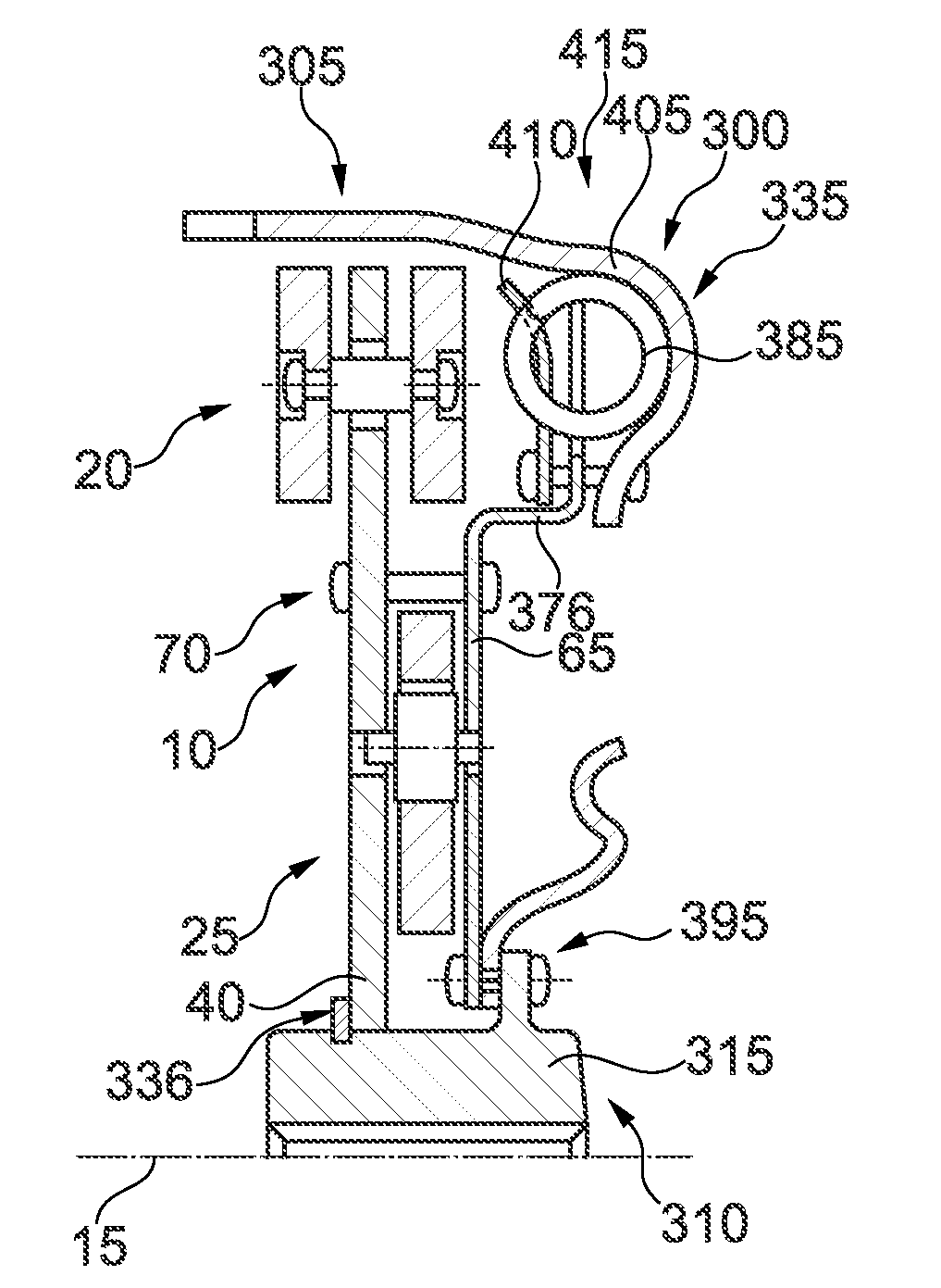
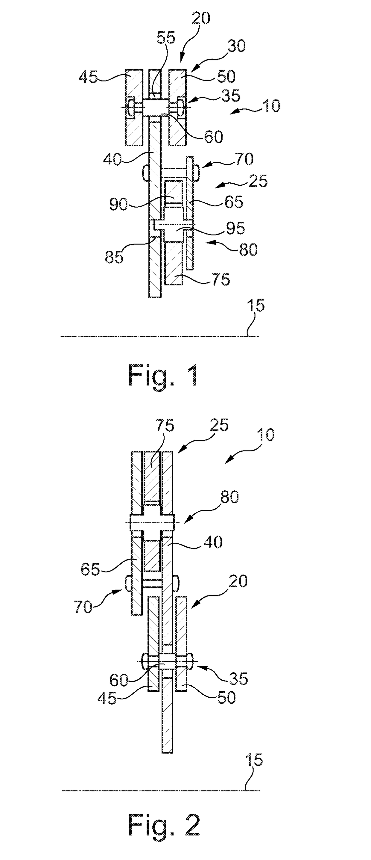
[0024]FIG. 1 shows a semi-longitudinal section through damper device 10 according to a Damper device 10 is supportable so that device 10 can rotate about axis of rotation 15. Damper device 10 comprises absorber device 20 and absorber device 25.

[0025]Absorber device 20 includes pendulum mass 30, coupling device 35 and flange part 40. Flange part 40 is of disk-shaped design, and extends essentially in a radial direction. Flange part 40 may be supported, for example, on the radially inner side of part 40 on a hub. Furthermore, it is also possible for flange part 40 to be connected torsionally to another unshown component of a drive system, or to damper device 10.

[0026]Pendulum mass 30 includes pendulum mass part 45 and pendulum mass part 50. Pendulum mass parts 45 and 50 are positioned on opposite sides of flange part 40, and are connected by means of coupling device 35 to flange part 40 so that parts 45 and 50 can move to a limited extent. Coupling device 35 is designed to guide pend...

second embodiment

[0032]FIG. 2 shows damper device 10 according to a Damper device 10 in FIG. 2 is similar in design to damper device 10 shown in FIG. 1. Differing therefrom, the arrangement of absorber device 20 and t absorber device 25 is transposed in the radial direction. Thus, absorber device 25 is positioned radially to the outside of absorber device 20. Furthermore, flange part 65 is positioned on the side opposite flange part 40, in reference to the arrangement in FIG. 1.

third embodiment

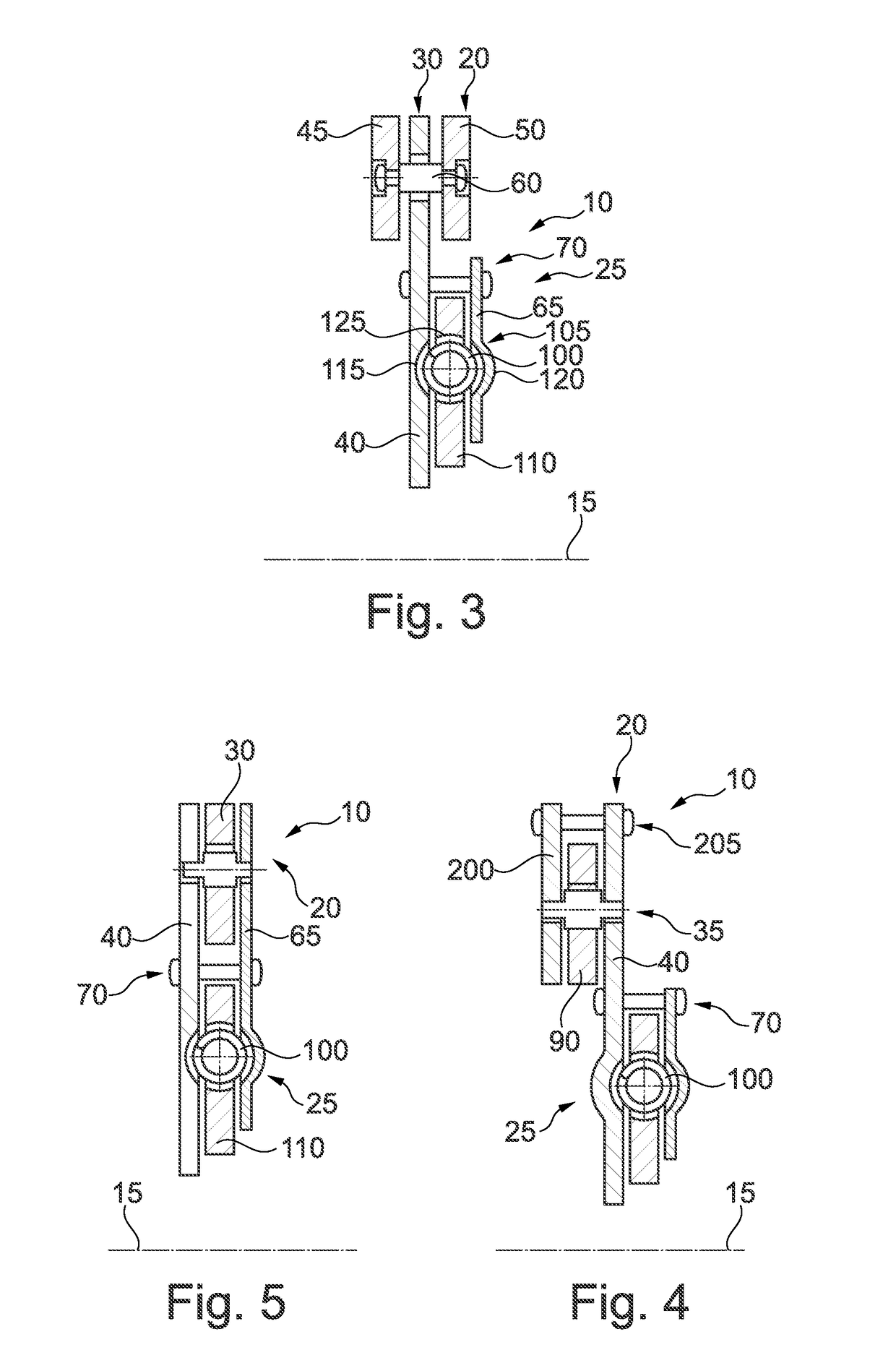
[0033]FIG. 3 shows a semi-longitudinal section through damper device 10 according to a Damper device 10 in FIG. 3 is similar in design to damper device 10 shown in FIG. 1. Differing therefrom, the design of absorber device 25 is dependent on frequency instead of on rotation speed. Absorber device 20 is designed as shown in FIG. 1.

[0034]Absorber device 25 has spring element 100 designed as an absorber element, receptacle 105 and absorber mass 110. Absorber mass 110 is positioned axially between flange part 40 and flange part 65. Receptacle 105 is formed by receptacle section 115, which is positioned in t flange part 40 in the shape of a partial circle, and by receptacle section 120, which is positioned in flange part 65 opposite receptacle section 115. Receptacle 105 here is designed corresponding to a form of spring element 100 on the circumference. Spring element 100 is positioned in the circumferential direction and / or tangentially to axis of rotation 15. In this embodiment, spri...


PUM


Abstract

A damper system which is supportable rotatably around an axis of rotation, having a first absorber device and a second absorber device. The first absorber device includes at least one first pendulum mass, a first coupling device and a first flange part. The first pendulum mass is coupled with the first flange part by means of the first coupling device. The first coupling device is designed to guide the first pendulum mass along a first oscillation path. The second absorber device is offset radially from the first absorber device. The second absorber device includes an absorber element. The absorber element is coupled with the first flange part.

Description

CROSS-REFERENCE TO RELATED APPLICATION[0001]The present application is the U.S. national stage application pursuant to 35 U.S.C. §371 of International Application No. PCT / DE2015 / 200413, filed Jul. 22, 2015, which application claims priority from German Patent Application No. DE 10 2014 214 519.8, filed Jul. 24, 2014, German Patent Application No. DE 10 2014 217 472.4, filed Sep. 2, 2014, and German Patent Application No. DE 10 2014 222 712.7, filed Nov. 6, 2014, which applications are incorporated herein by reference in their entireties.TECHNICAL FIELD[0002]The invention relates to a damper system with radially offset absorber devices.BACKGROUND[0003]Damper systems for eliminating rotational non-uniformities in a drivetrain of a motor vehicle are known.SUMMARY[0004]According to the present disclosure, it has been recognized that an improved damper system can be provided by the damper system being supportable so that it can rotate about an axis of rotation. The damper system includes...

Claims


Application Information

Patent Timeline
Patent Type & Authority Applications(United States)
IPC IPC(8): F16F15/134
CPCF16F15/13469F16F15/1407F16F15/145
Inventor MAIENSCHEIN, STEPHANHUEGEL, CHRISTIAN
Owner SCHAEFFLER TECH AG & CO KG
Why Eureka
Try Eureka