Target Detection Apparatus and Target Detection Method

Active Publication Date: 2017-06-22
NISSAN MOTOR CO LTD
View PDF7 Cites 7 Cited by
  • Summary
  • Abstract
  • Description
  • Claims
  • Application Information

AI Technical Summary

Benefits of technology

The present invention aims to provide a target detection device and method that can accurately detect targets.

Problems solved by technology

The error is affected greatly by the surrounding situation of the vehicle.
If the error is large, the traffic indicator will be outside the image processing area and therefore will be undetectable.
On the other hand, setting an excessively large image processing area increases the possibility of erroneously detecting an object other than the traffic indicator.

Method used


Image

  • Target Detection Apparatus and Target Detection Method
  • Target Detection Apparatus and Target Detection Method
  • Target Detection Apparatus and Target Detection Method

Examples


first embodiment

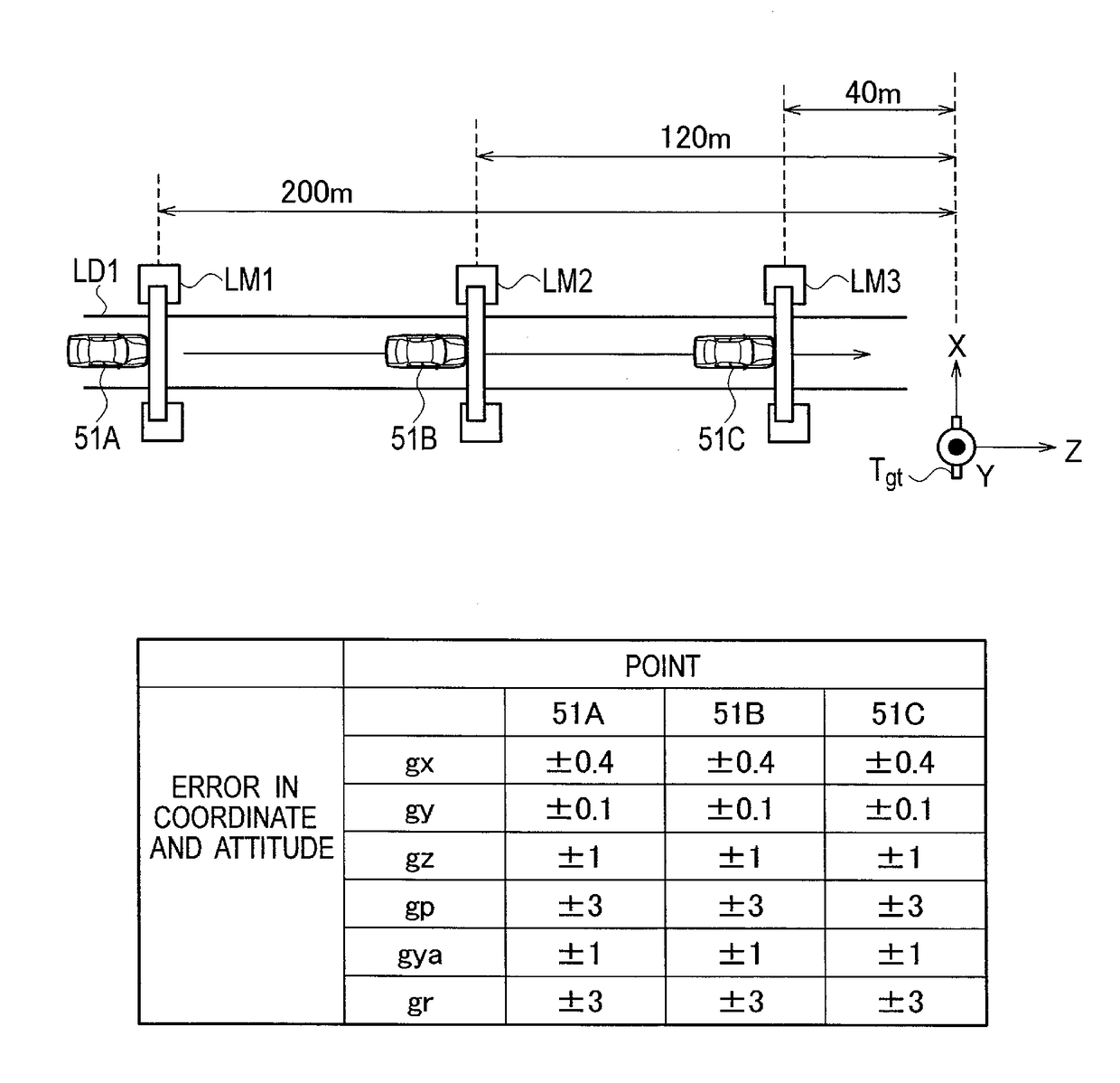
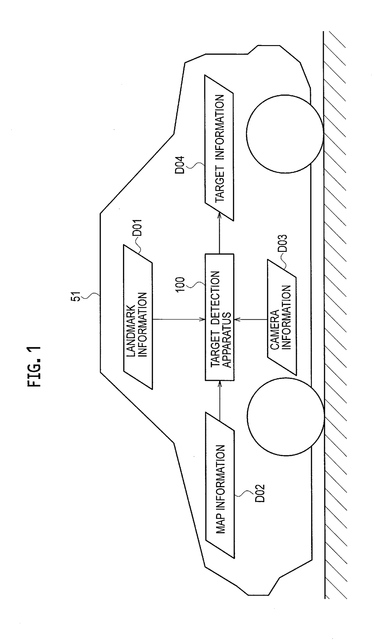
[0025]With reference to FIG. 1, a description is given of information inputted to and outputted from a target detection apparatus 100 of the present embodiment. The target detection apparatus 100 detects a target placed near a road, from an image taken by an imager (camera) mounted in a vehicle 51. The target is fixed onto the ground and includes, for example, a traffic signal and a road sign. In the embodiments herein, a traffic signal is used as an example.

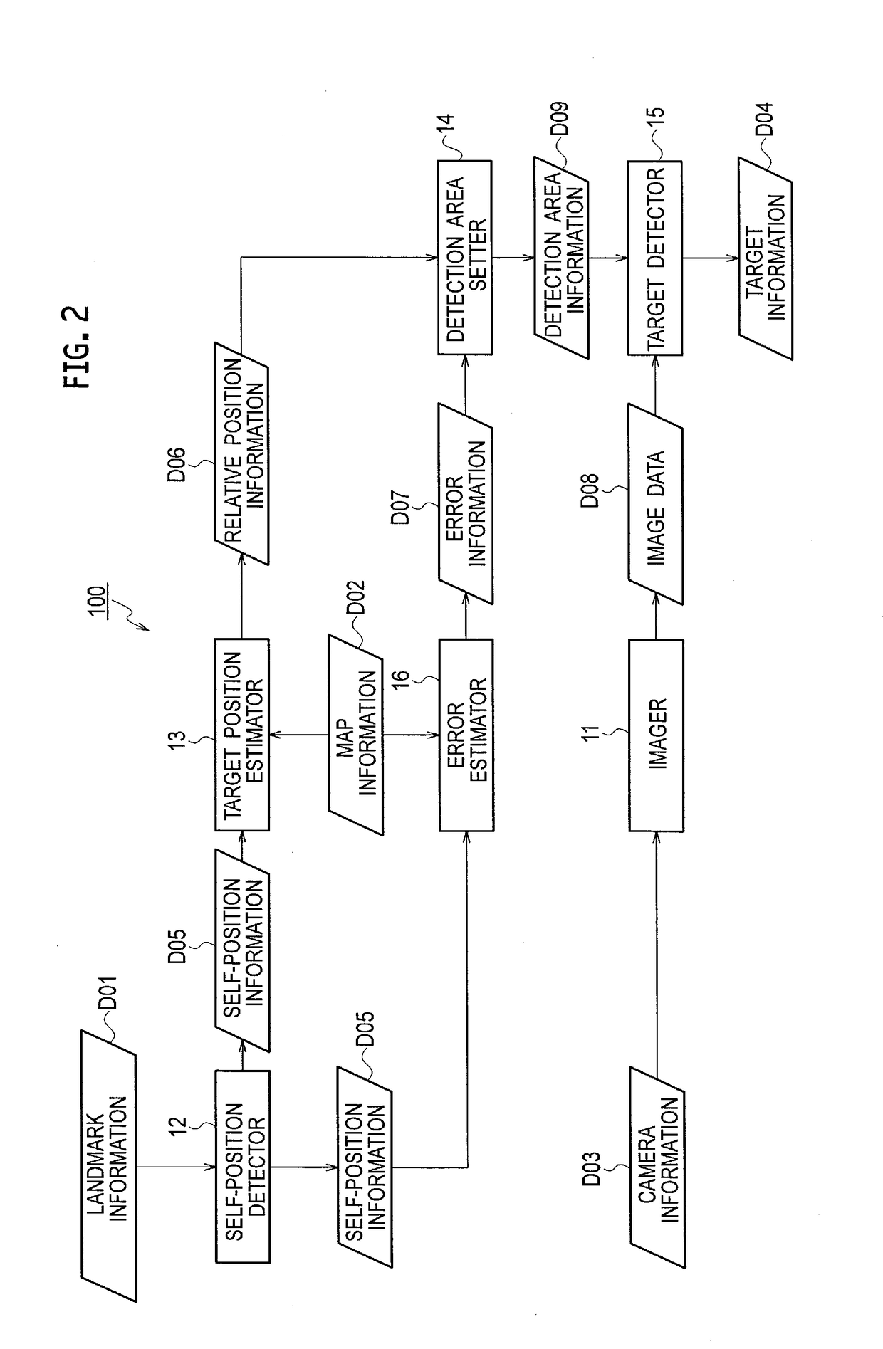
[0026]The target detection apparatus 100 receives input of map information D02, landmark information D01, and camera information D03. The map information D02 contains positional information on a target, in which a position on a map and a position in an actual environment are associated with each other beforehand. The landmark information D01 is used to calculate the self-position of the vehicle 51 in the actual environment. Landmarks include a characteristic object on the ground (terrestrial landmarks) and a Global Positioning S...

second embodiment

[0073]A second embodiment is described taking an example where the self-position is detected using, instead of a landmark, a GPS satellite that transmits GPS signals receivable by the vehicle 51. The self-position detector 12 receives a GPS signal as the landmark information D01 and detects an initial position (initial coordinates and initial attitude) of the vehicle 51 from the GPS signal.

[0074]The vehicle 51 might not be able to receive GPS signals due to the environment of the vehicle, for example, when there are many buildings surrounding the vehicle to block the GPS signals. In such a case, the self-position detector 12 calculates the self-position of the vehicle by accumulatively adding the amount of movement of the vehicle to the initial position detected by the initial position detector 21.

[0075]The initial position detector 21 in FIG. 3 detects the initial position of the vehicle 51 using a GPS signal. The initial position is the position, i.e., the coordinates and attitude...


PUM


Abstract

A target detection apparatus acquires an image by imaging the surroundings of a vehicle, detects a self-position of the vehicle based on an amount of movement of the vehicle from an initial position thereof, and estimates a relative position of a target, located around the vehicle, with respect to the vehicle based on the self-position and information on a position of the target on a map. The target detection apparatus sets a detection area for the target within the image based on the relative position of the target with respect to the vehicle, and detects the target from the detection area. The target detection apparatus estimates error contained in the self-position based on the amount of movement of the vehicle from the initial position, and adjusts the size of the detection area for the target according to the error.

Description

TECHNICAL FIELD[0001]The present invention relates to a target detection apparatus and a target detection method.BACKGROUND[0002]An image processing system that detects a traffic indicator from image data on a scene ahead of a vehicle is conventionally known (Japanese Patent Application Publication No. 2007-241469). Japanese Patent Application Publication No. 2007-241469 detects the position and attitude of a vehicle to thereby predict the position of a traffic indicator, determines an image processing area within image data based on the predicted position, and detects the traffic indicator from the image processing area. The image processing system thus decreases the image processing load.[0003]The image processing system of Japanese Patent Application Publication No. 2007-241469, however, does not consider error in the detected position and attitude of the vehicle when determining the image processing area. The error is affected greatly by the surrounding situation of the vehicle....

Claims


Application Information

Patent Timeline
IPC IPC(8): G06K9/00G06K9/20G06T7/73G01C21/30G06K9/32G06V10/98
CPCG06K9/00825G01C21/30G06K9/3233G06T2207/30252G06K9/2054G06K9/00818G06T7/74G08G1/09623G06V20/588G06V20/582G06V10/98G06V20/584
Inventor YAMANOI, DAIKINISHIUCHI, HIDEKAZUANDOU, TOSHIYUKISATOH, HIROSHIMATSUO, HARUO
Owner NISSAN MOTOR CO LTD
Why Eureka
Try Eureka