Antenna orientation adjustment device and antenna orientation adjustment method

a technology of antenna orientation and adjustment device, which is applied in the direction of receiving monitoring, transmission monitoring, transmitter monitoring, etc., can solve the problems of time-consuming and laborious set-up of antenna, and it is difficult in practice to set the antenna orientation (i.e., orient the antenna) toward the direction, so as to achieve quick and accurate installation of antenna devi

Inactive Publication Date: 2017-06-22
NEC CORP
View PDF5 Cites 16 Cited by
  • Summary
  • Abstract
  • Description
  • Claims
  • Application Information

AI Technical Summary

Benefits of technology

[0016]According to the exemplary aspects of the present invention, it is possible to quickly and accurately install an antenna device.

Problems solved by technology

However, because two orientations, the elevation and the azimuth, need to be set to adjust the antenna orientation, it is extremely difficult in practice to set the antenna orientation (i.e., orientate the antenna) toward the direction in which the maximum reception level can be achieved.
It is time-consuming work to set the antenna toward the direction with the maximum reception level in a step-by-step manner by making a fine adjustment of the elevation and the azimuth by checking the reception level each time.

Method used


Image

  • Antenna orientation adjustment device and antenna orientation adjustment method
  • Antenna orientation adjustment device and antenna orientation adjustment method
  • Antenna orientation adjustment device and antenna orientation adjustment method

Examples


first exemplary embodiment

[0042]A first exemplary embodiment of the invention is described hereinafter.

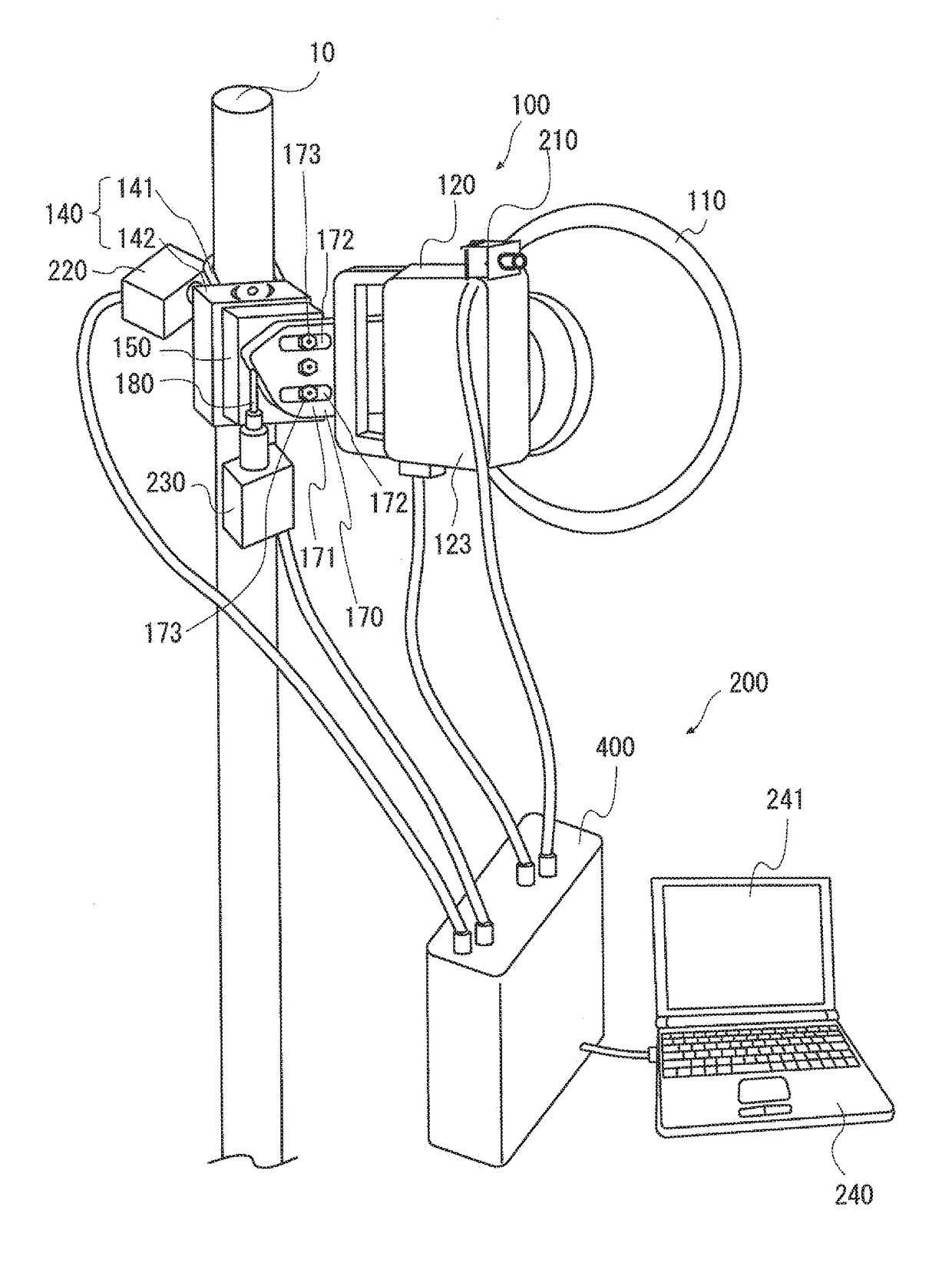
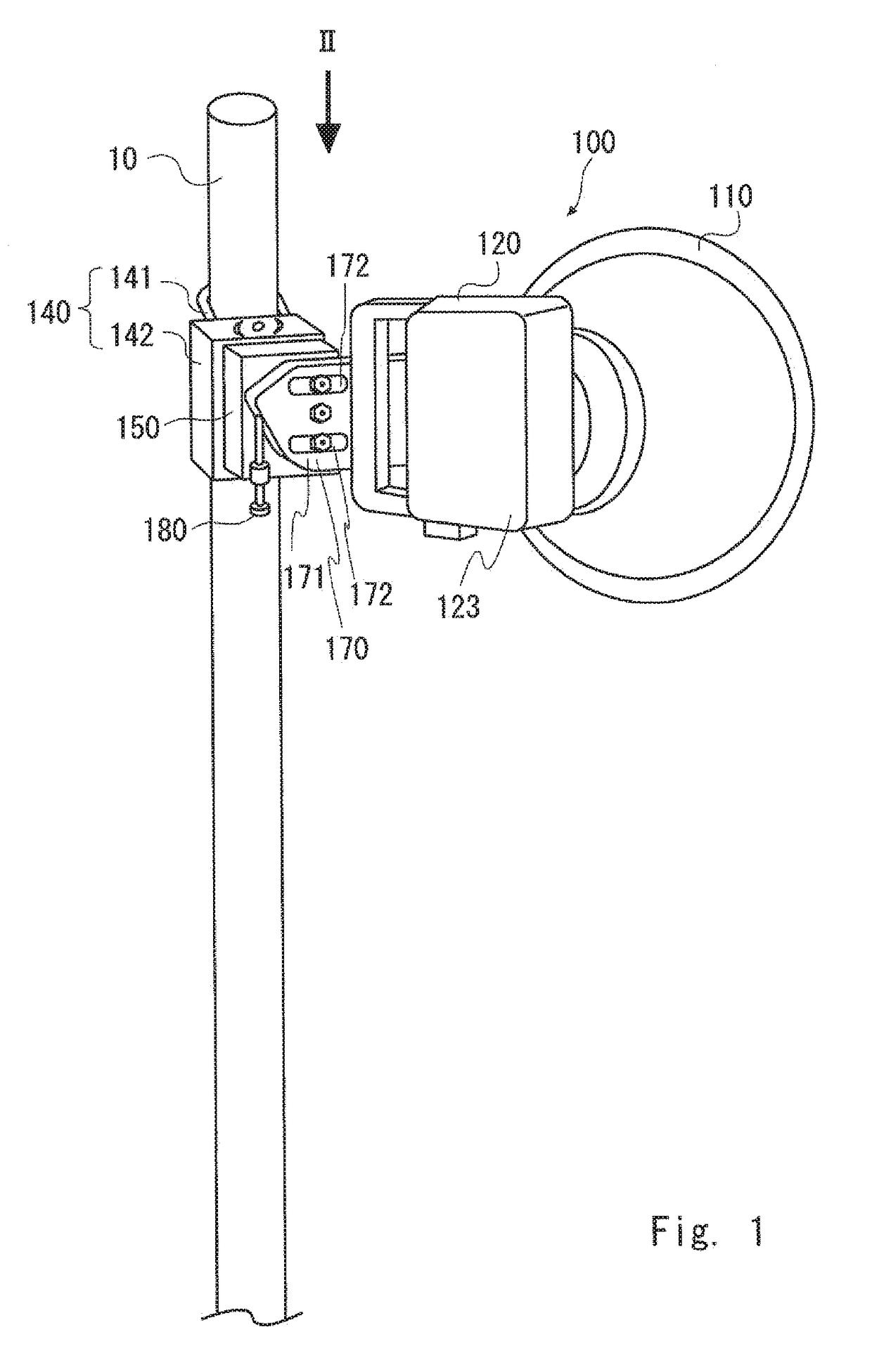
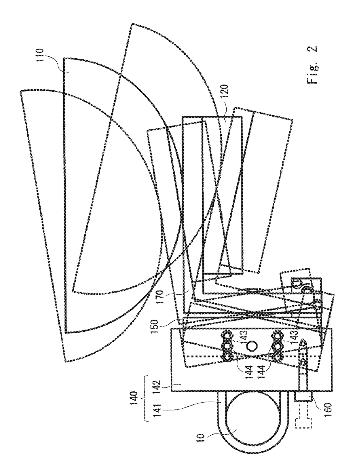
[0043]A principal point of this exemplary embodiment is the structure and the operation of an antenna orientation adjustment device that adjusts the orientation of an antenna. However, prior to describing the adjustment of the antenna orientation, the structure of an antenna device 100 is schematically described hereinafter.

[0044]FIG. 1 is a view showing the antenna device 100. The antenna device 100 may be a known one. Although a so-called parabolic antenna is shown as an example, the type of the antenna is not particularly limited in the application of this exemplary embodiment. A directional antenna may be a planar antenna, for example.

[0045]FIG. 1 shows the antenna device 100 mounted on a mast 10 viewed from the back. The antenna device 100 includes an antenna unit 110, a transmitting and receiving unit 120, and a mounting means 130.

[0046]The antenna unit 110 is a parabolic antenna in this example. The ...


PUM


Abstract

An antenna orientation adjustment device (200) include a camera (210), nut runners (220 and 230), and a motion controller (400). The nut runners (220 and 230) can be mounted on an azimuth adjustment bolt (160) and an elevation adjustment bolt (180), respectively. The nut runners (220 and 230) change the orientation of an antenna unit by applying motor power to the azimuth adjustment bolt (160) and the elevation adjustment bolt (180). The motion controller (400) calculates an angle position of the antenna unit (110) where a reception strength is maximum based on an image taken by the camera (210) and a reception strength of radio waves received by the antenna unit (110), and then adjusts the antenna unit (110) to the angle position where the reception strength is maximum by supplying a drive signal to the azimuth adjustment bolt (160) and the elevation adjustment bolt (180).

Description

TECHNICAL FIELD[0001]The present invention relates to an antenna orientation adjustment device and an antenna orientation adjustment method that adjust the orientation of an antenna.BACKGROUND ART[0002]When installing a directional antenna, it is important to place it so that it is orientated toward an appropriate direction in order to maximize the reception level. Currently, when adjusting the antenna orientation, a worker seeks to determine the orientation with the maximum reception level by a process of trial and error in which the antenna orientation is changed in a step-by-step manner and installs the antenna at that orientation.[0003]However, because two orientations, the elevation and the azimuth, need to be set to adjust the antenna orientation, it is extremely difficult in practice to set the antenna orientation (i.e., orientate the antenna) toward the direction in which the maximum reception level can be achieved. It is time-consuming work to set the antenna toward the dir...

Claims


Application Information

Patent Timeline
Patent Type & Authority Applications(United States)
IPC IPC(8): H01Q1/12H04B17/10H04B17/27H01Q3/02
CPCH01Q1/1257H04B17/27H04B17/102H01Q3/02H01Q3/005H04B17/101H04B17/12H04B17/318
Inventor HIRABE, MASASHI
Owner NEC CORP
Why Eureka
Try Eureka