Stack-like multi-junction solar cell

Pending Publication Date: 2017-06-29
AZUR SPACE SOLAR POWER
View PDF3 Cites 2 Cited by
  • Summary
  • Abstract
  • Description
  • Claims
  • Application Information

AI Technical Summary

Benefits of technology

[0021]Surprisingly, depending on the precise design of the multi-junction solar cell, a slight lowering of the BOL efficiency can also be accepted by using

Problems solved by technology

However, using a bonding process as the manufacturing process is cost-intensive and redu

Method used


Image

  • Stack-like multi-junction solar cell
  • Stack-like multi-junction solar cell

Examples


Example

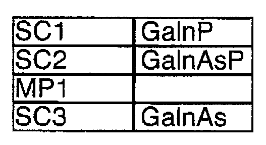
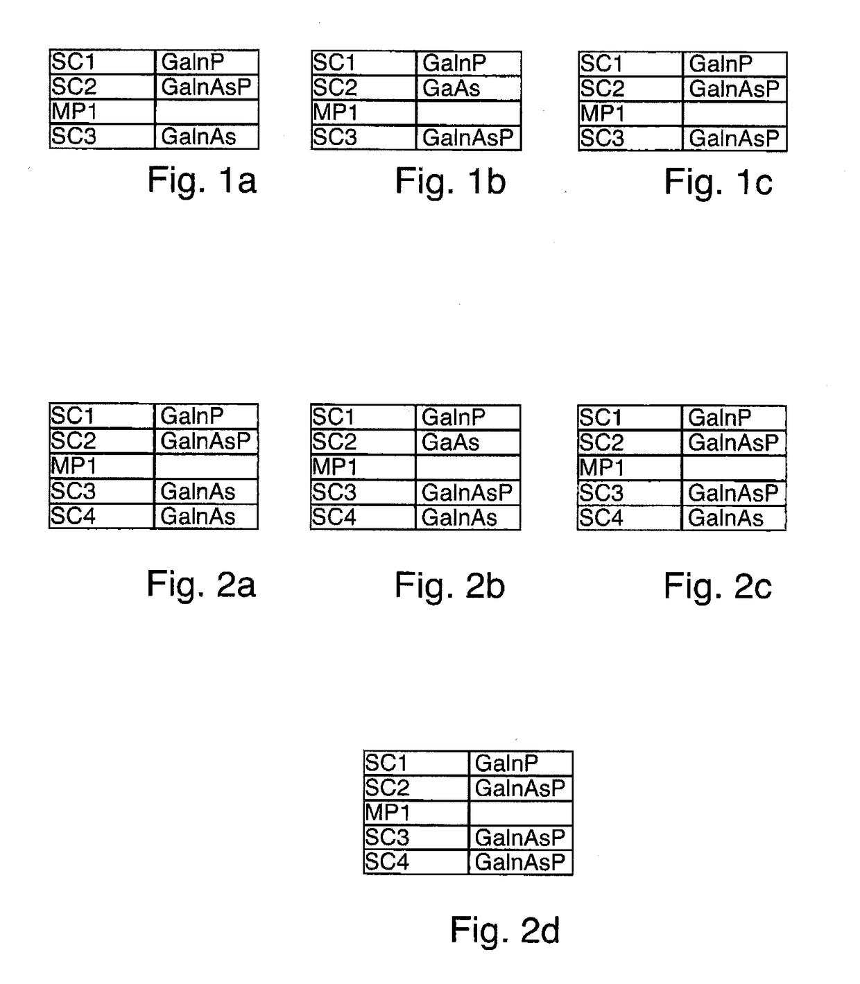
[0047]The illustration in FIG. 1a shows a cross section of an embodiment according to the invention of a stack-like monolithic multi-junction solar cell MS; in the following, the individual solar cells of the stack are referred to as a partial cell. The multi-junction solar cell MS has a first partial cell SC1, wherein the first partial cell SC1 formed of a GaInP compound and has the largest band gap of the entire stack above 1.75 eV. A second partial cell SC2, formed of a GaInAsP compound, is arranged underneath the first partial cell SC1. The second partial cell SC2 has a smaller band gap than the first partial cell SC1. Under the second partial cell SC2, a third partial cell SC3 formed of an InGaAs compound is arranged under the second partial cell SC2, wherein the third partial cell SC3 has the smallest band gap. In the present case, the third partial cell SC3 has an energy band gap of less than 1.25 eV.

[0048]A metamorphic buffer MP1 is formed between the second partial cell SC2...


PUM


Abstract

A multi-junction solar cell having at least three partial cells having an emitter and a base. The first partial cell comprises a first layer of a compound containing at least the elements GaInP, and the energy band gap of the first layer is greater than 1.75 eV, and wherein the second partial cell has a second layer of a compound having at least the elements GaAs and the lattice constant of the second layer is in the range between 5.635 Å and 5.675 Å, and wherein the third partial cell has a third layer of a compound having at least the elements GaInAs and the energy band gap of the third layer is smaller than 1.25 eV and the lattice constant of the third layer is greater than 5.700 Å.

Description

[0001]This nonprovisional application claims priority under 35 U.S.C. §119(a) to German Patent Application No. 10 2015 016 822.3, which was filed in Germany on Dec. 25, 2015, and which is herein incorporated by reference.BACKGROUND OF THE INVENTION[0002]Field of the Invention[0003]The invention relates to a stack-like multi-junction solar cell.[0004]Description of the Background Art[0005]An inverted metamorphic four-junction solar cell (IMM4J) with a beginning-of-life (BOL) efficiency of approx. 34% (AMO) and a relatively low end-of-life (EOL) residual factor of approx. 82% as compared to commercially available triple-junction solar cells is known from the publication “Experimental Results from Performance Improvement and Radiation Hardening of Inverted Metamorphic Multi-Junction Solar Cells” by Patel et al., Proceedings of 37th IEEE PVSC, Seattle (2011). The epitaxial deposition on the growth substrate is here inverted in comparison with the application and orientation of the solar...

Claims


Application Information

Patent Timeline
IPC IPC(8): H01L31/0687H01L31/0304H01L31/054H01L31/0693
CPCH01L31/06875H01L31/0693H01L31/0547H01L31/03042H01L31/03046H01L31/0725H01L31/0735H01L31/0745Y02E10/544Y02E10/52Y02P70/50H01L31/041
Inventor GUTER, WOLFGANGMEUSEL, MATTHIASROESENER, TOBIAS
Owner AZUR SPACE SOLAR POWER
Why Eureka
Try Eureka