
Shot-blasting apparatus

a technology of a shotblasting apparatus and a projection chamber, which is applied in the direction of metal-working apparatus, manufacturing tools, abrasive machine accessories, etc., can solve the problems of large amount of powder dust generated in the projection chamber, and achieve the effect of efficient dust collection and ventilation of the insid

Active Publication Date: 2017-07-06
SINTOKOGIO LTD
View PDF9 Cites 0 Cited by
  • Summary
  • Abstract
  • Description
  • Claims
  • Application Information

AI Technical Summary

Benefits of technology

The patent text describes a new technology that allows for better control of heating and cooling in a device. This technology can improve the performance and reliability of the device.

Problems solved by technology

In the shot-blasting apparatus, due to collision of shots against the workpiece in the projection chamber, a large amount of powder dust is inevitably generated in the projection chamber.

Method used


Image

  • Shot-blasting apparatus
  • Shot-blasting apparatus
  • Shot-blasting apparatus

Examples


Embodiment Construction

[0036]With reference to the drawings, a shot-blasting apparatus according to a preferred embodiment of the present invention will now be described.

[0037]FIG. 3 is a horizontal sectional view showing the shot-blasting apparatus according to this embodiment. The shot-blasting apparatus according to this embodiment is a type configured to project shots onto a workpiece disposed in a projection chamber, to thereby process the workpiece.

[0038]The shot-blasting apparatus comprises a cabinet 10, and a rotary hanger 11 disposed within the cabinet 10. The rotary hanger 11 is a drum-shaped (cylindrical-shaped) rotary hanger disposed such that a longitudinal axis thereof is oriented in a vertical direction. The rotary hanger 11 is configured to be rotated about the longitudinal axis by a rotational drive mechanism.

[0039]The rotary hanger 11 comprises a top plate and a bottom plate attached, respectively, at an upper end and a lower end thereof. The rotary hanger 11 has a columnar internal spac...


PUM


Abstract

Provided is a shot-blasting apparatus which is capable of efficiently perform dust collection and ventilation of an inside of a projection chamber, even using a dust collector having a small-size and low-cost suction device. The shot-blasting apparatus comprises: a cabinet (10); a plurality of process chambers (13a, 13b) provided inside the cabinet in such a manner that each of the process chambers is capable of housing a workpiece therein and selectively movable between a carry-in-and-out position and a projection position; an air inlet port (19) for introducing external air into each of the process chambers therethrough; and an air outlet port provided at a position opposed to the air inlet port across the process chamber set at the projection position, and linearly communicated with an internal space of the process chamber set at the projection position, wherein, according to suction from the air outlet port, air is caused to flow from the air inlet port into the process chamber set at the projection position, and led to the air outlet port while passing through the process chamber set at the projection position.

Description

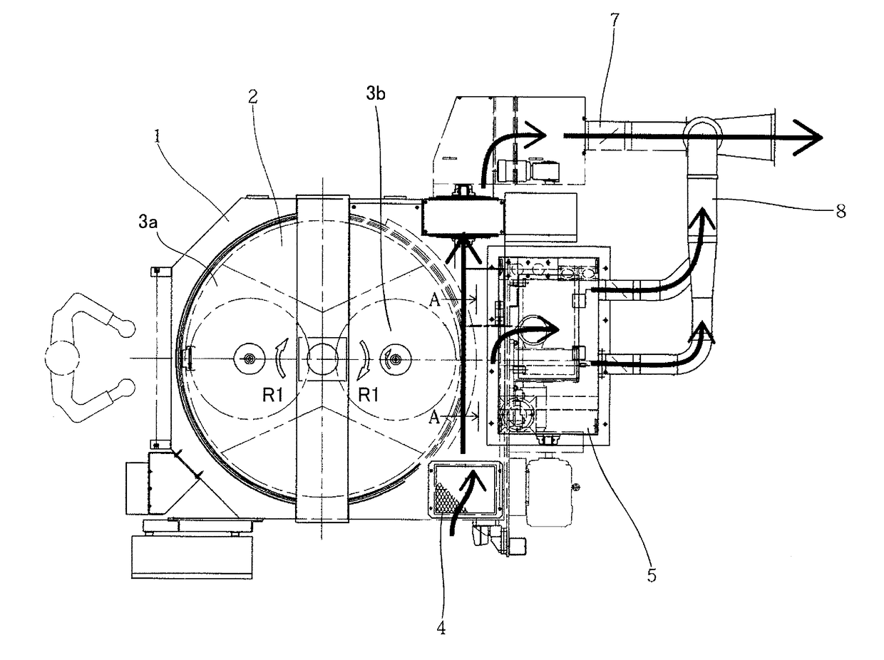
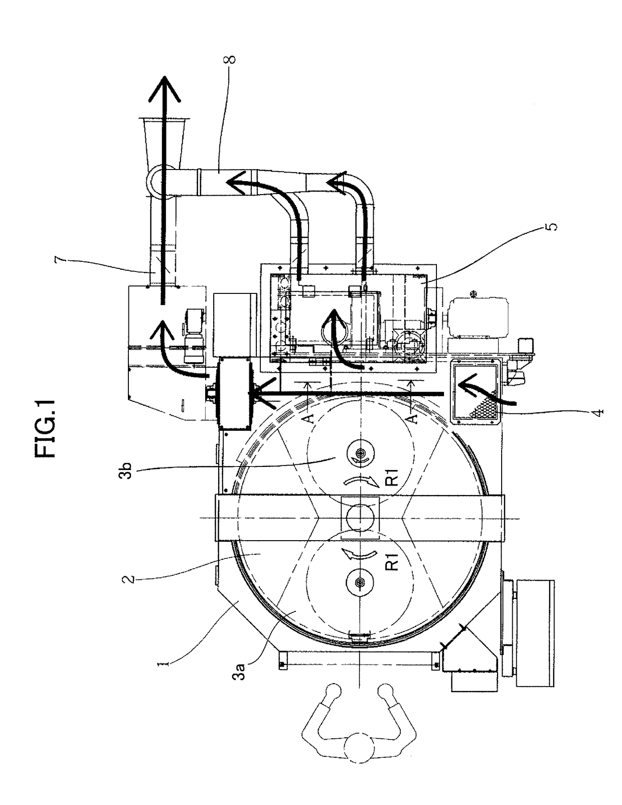
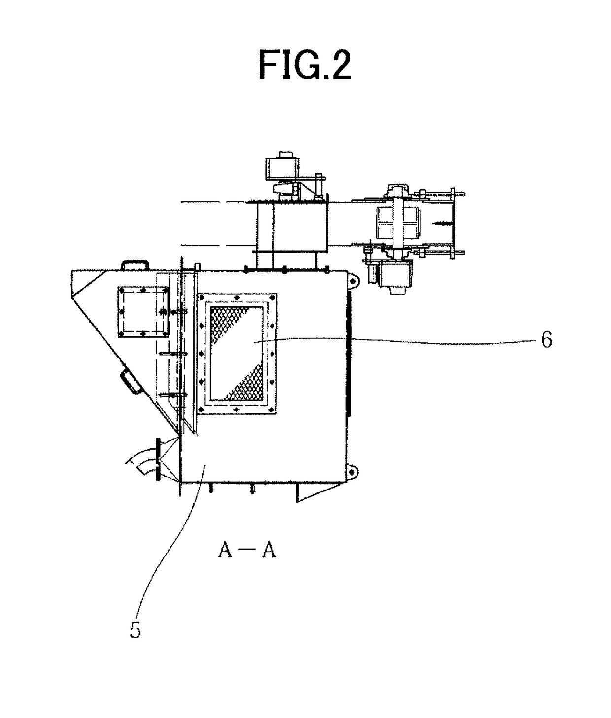
TECHNICAL FIELD[0001]The present invention relates to a shot-blasting apparatus, and more specifically to a shot-blasting apparatus configured to project shots onto a workpiece.BACKGROUND ART[0002]There has been known a shot-blasting apparatus configured to project shots onto a workpiece disposed in a projection chamber to process a workpiece (see the following Patent Document 1). In the shot-blasting apparatus, due to collision of shots against the workpiece in the projection chamber, a large amount of powder dust is inevitably generated in the projection chamber. Therefore, such powder dust generated in the projection chamber is collected by a dust collector to thereby keep a working environment around the apparatus clean.[0003]As an example of the shot-blasting apparatus, a type shown in FIGS. 1 and 2 is commonly known. This type of shot-blasting apparatus comprises a cabinet 1, and a rotary hanger 2 installed inside the cabinet 1. The rotary hanger 2 is equipped with a hanger ho...

Claims


Application Information

Patent Timeline
Patent Type & Authority Applications(United States)
IPC IPC(8): B24C9/00B24C3/20
CPCB24C3/20B24C9/003B24C3/24B24C9/00
Inventor YAMAMOTO, SHOICHIKOYAMA, TAKUYA
Owner SINTOKOGIO LTD
Learn More