Multi-rotor UAV with compact folding rotor arms

a multi-rotor, compact technology, applied in the field of drones, can solve the problems of reducing affecting the folding efficiency of the rotor arms,

Active Publication Date: 2017-07-13
DRAGANFLY INNOVATIONS
View PDF0 Cites 24 Cited by
  • Summary
  • Abstract
  • Description
  • Claims
  • Application Information

AI Technical Summary

Benefits of technology

[0089]Since all the rotor arms 306.1 to 306.6 are moved in two planes perpendicular to the central vertical axis, the attachment interface 320 can be directly mounted to the body 102, obviating the connecting columns 108

Problems solved by technology

One of the current limitations however is that present attachment interfaces such as those disclosed in US Patent Applications 2010/108801 and 2012/13873 still leave the folded rotor arms extending outward from the body on one side thereof, making

Method used


Image

  • Multi-rotor UAV with compact folding rotor arms
  • Multi-rotor UAV with compact folding rotor arms
  • Multi-rotor UAV with compact folding rotor arms

Examples


Embodiment Construction

Description

[0060]Unless defined otherwise, all technical and scientific terms used herein have the same meaning as commonly understood by one of ordinary skill in the art to which the invention belongs. Although any methods and materials similar or equivalent to those described herein can be used in the practice or testing of the present invention, the preferred methods and materials are now described.

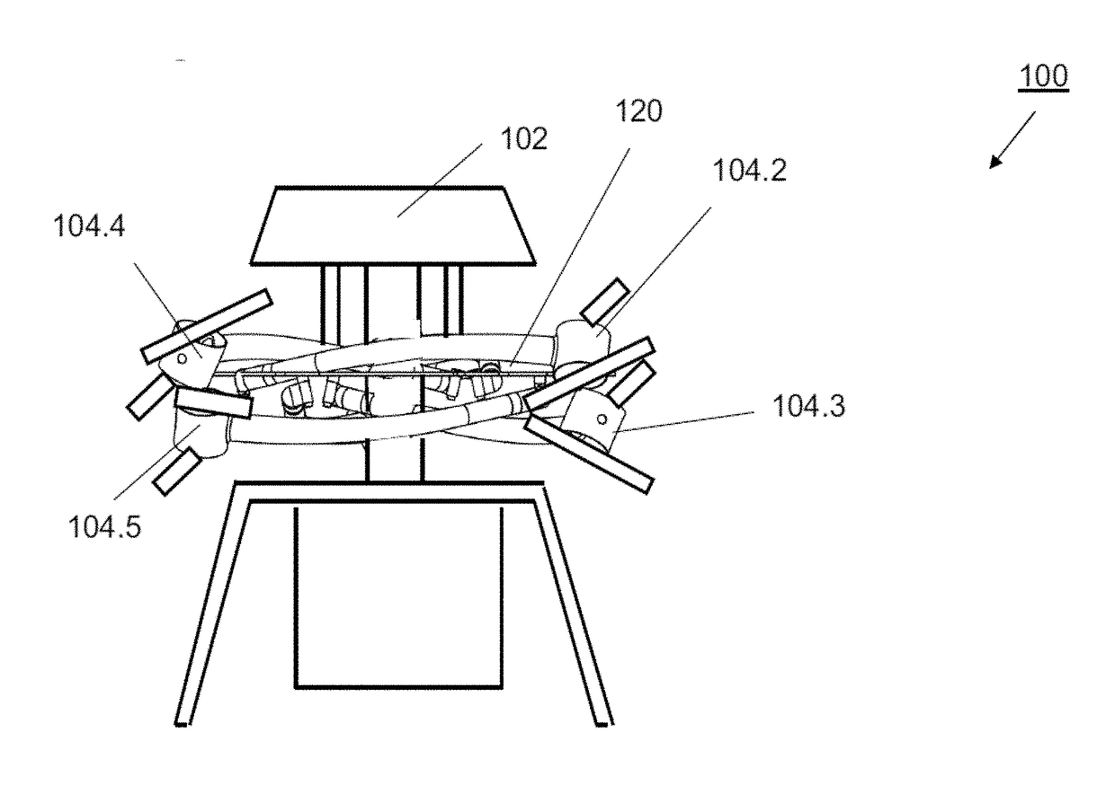
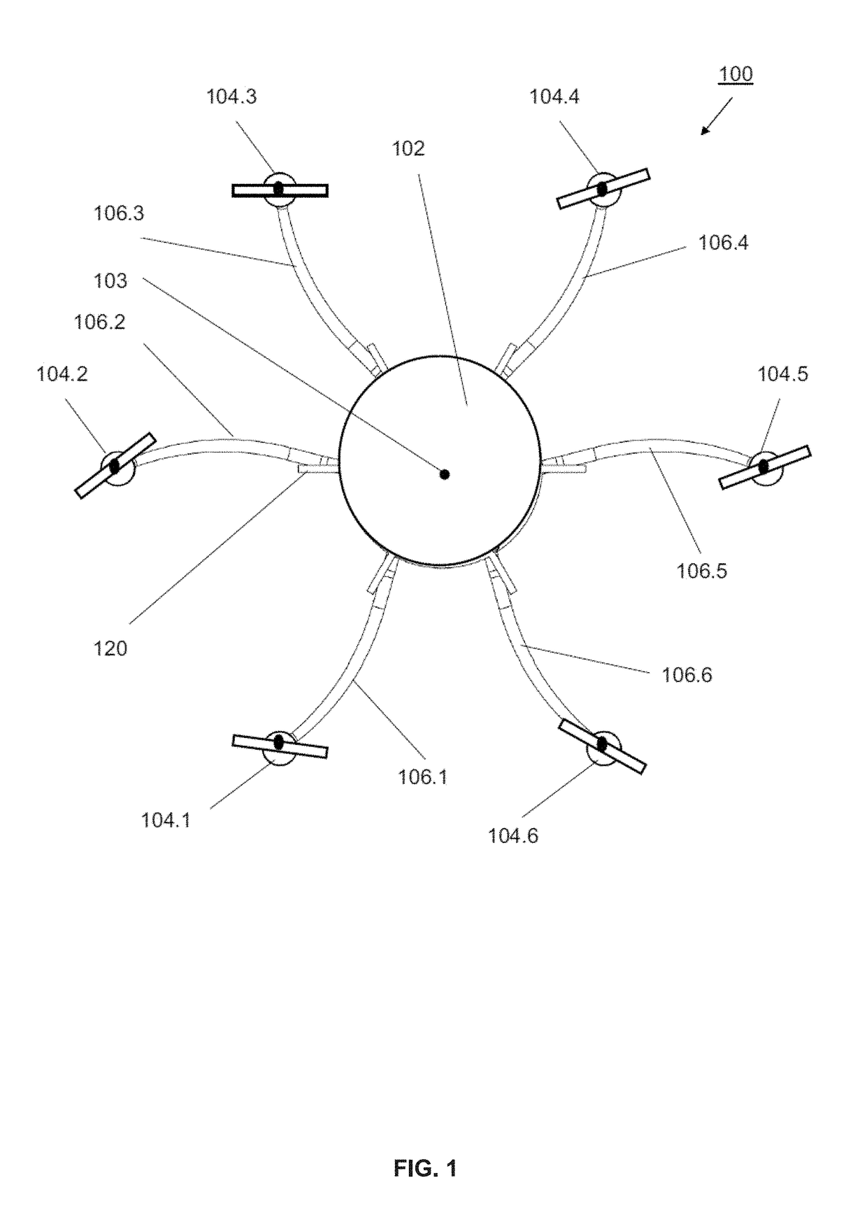
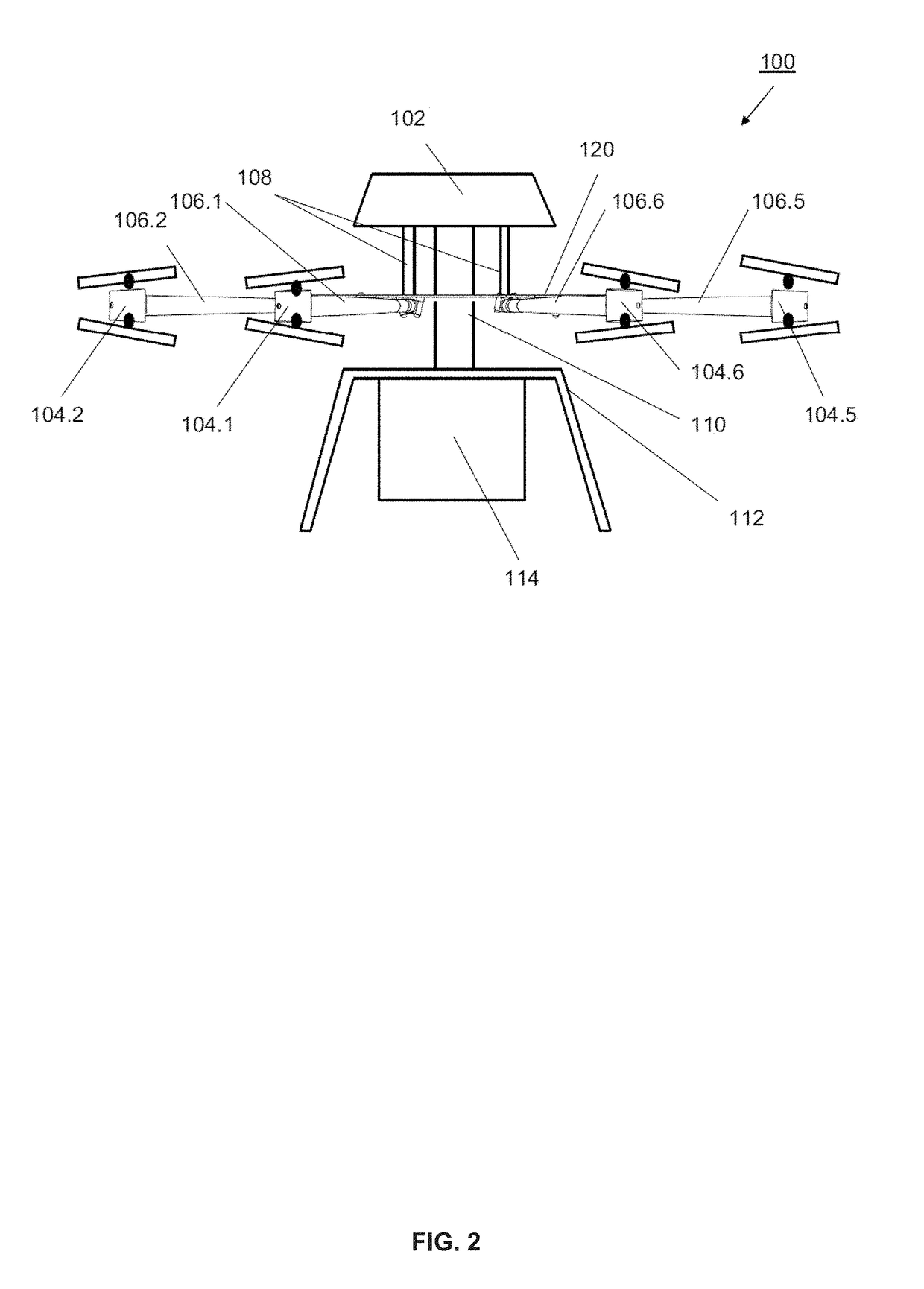
[0061]The invention comprises a multi-rotor UAV which has an unfolded operating position and a folded storage or transport position, The multi-rotor UAV of the present invention, when in its folded position, is collapsed further, with the rotor arms and rotor assemblies in closer proximity to the body and each other, than in prior art multi-rotor UAV configurations, yielding a better stored and transported unit that is less likely to sustain damage when in the folded position.

[0062]Referring first to FIG. 1 through FIG. 4, there is shown one exemplary embodiment of a multi-rotor UAV 10...


PUM


Abstract

A multi-rotor UAV comprises a body and a plurality of rotor arms extending radially from the body. A rotor assembly is connected to an outside end of each rotor arm. An attachment interface is connected to the body and provides rotor arm attachment points for attaching the rotor arms to the body and pivoting the rotor arms from an unfolded operating position, to a folded position wherein the rotor arms are pivoted such that an outer arm portion of each rotor arm is enabled to cross the pivot end and an inner arm portion of an adjacent or arm.

Description

BACKGROUND[0001]Field of the Invention[0002]The present invention relates to unmanned aerial vehicles(UAVs), also referred to as “drones”, with compact folding rotor arms.[0003]Background of the Invention[0004]In the past number of years there has been increased awareness and use of UAVs in many applications from consumer through to commercial and safety applications. Such aerial missions include, for example, surveillance with associated data acquisition and one-way delivery of small payloads. Typically, rotary wing type UAVs are preferred over fixed wing aircraft due to: the ability to vertically takeoff and land from a static position; the ability to hover; the ability to move sideways; and, the ability to quickly transition between the different types of movement.[0005]More recently, multi-rotor UAV designs using a plurality of pairs of fixed pitched propellers—with one propeller rotating clockwise and one propeller rotating counter-clockwise—are employed in numerous designs of ...

Claims


Application Information

Patent Timeline
IPC IPC(8): B64C11/46B64C39/02B64C27/08
CPCB64C11/46B64C2201/024B64C39/024B64C27/08B64U50/19B64U30/293B64U10/16B64U60/50B64C1/30B64U10/10B64U10/13
Inventor WOOD, GREG
Owner DRAGANFLY INNOVATIONS
Why Eureka
Try Eureka