
Range finder and range correction device correction parameters

a range finder and range correction technology, applied in the field of range finder and range correction device correction parameters, can solve the problems of likely impairment of the calibrated state, horizontal and vertical displacement of stereo images, etc., and achieve the effects of preventing accuracy of ranging, enhancing the accuracy of ranging, and maintaining and improving ranging accuracy

Inactive Publication Date: 2017-07-13
DENSO CORP +1
View PDF4 Cites 15 Cited by
  • Summary
  • Abstract
  • Description
  • Claims
  • Application Information

AI Technical Summary

Benefits of technology

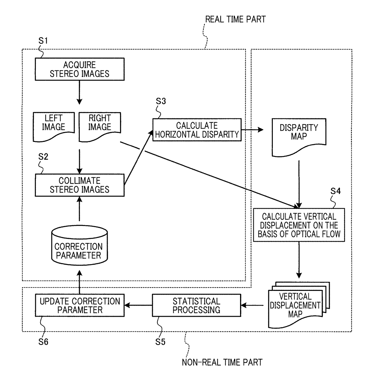
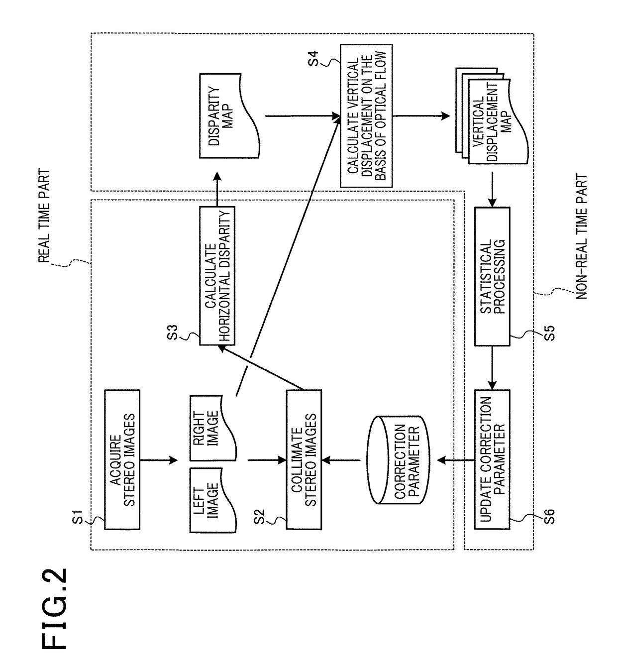
The patent text describes a method for improving the accuracy of ranging by using stereo images and correction parameters. The correction parameters are used to align the stereo images and compensate for vertical displacement between them. After the correction, the horizontal disparity between the stereo images is calculated to enhance ranging accuracy. The distribution of vertical displacements between the stereo images is also calculated to update the old correction parameters. This allows the correction parameters to be updated relevantly with the latest situation, preventing the accuracy of ranging to decline over time.

Problems solved by technology

However, actually, horizontal and vertical displacements are caused in the stereo images by the displacement between the mounting positions of the stereo cameras or by the shape of the camera lenses.
However, the calibrated state is likely to be impaired with time being influenced by vibrations or the like.

Method used


Image

  • Range finder and range correction device correction parameters
  • Range finder and range correction device correction parameters
  • Range finder and range correction device correction parameters

Examples


examples

[0050][Calculation Examples]

[0051]FIG. 3A is an image of distribution of vertical displacements between stereo images obtained by statistically processing vertical displacement maps calculated from 300 frames of stereo images. The image expresses the degree of vertical displacement with a gray scale. Darker gray means greater amount of vertical displacement. In the example of FIG. 3A, the vertical displacement is large in the upper-right and lower-left portions of the image, and is particularly noticeable in the upper-right portion.

[0052]FIG. 3B are photographs showing an image 31 of a ranging target captured by the stereo camera 10 having the vertical displacements shown in FIG. 3A, a distance image 32 of distance calculation conducted for the image 31 without correcting the vertical displacements, and a distance image 33 of distance calculation conducted for the image 31 after correcting the vertical displacements.

[0053]As shown in FIG. 3B, in the distance image 32 without correct...


PUM


Abstract

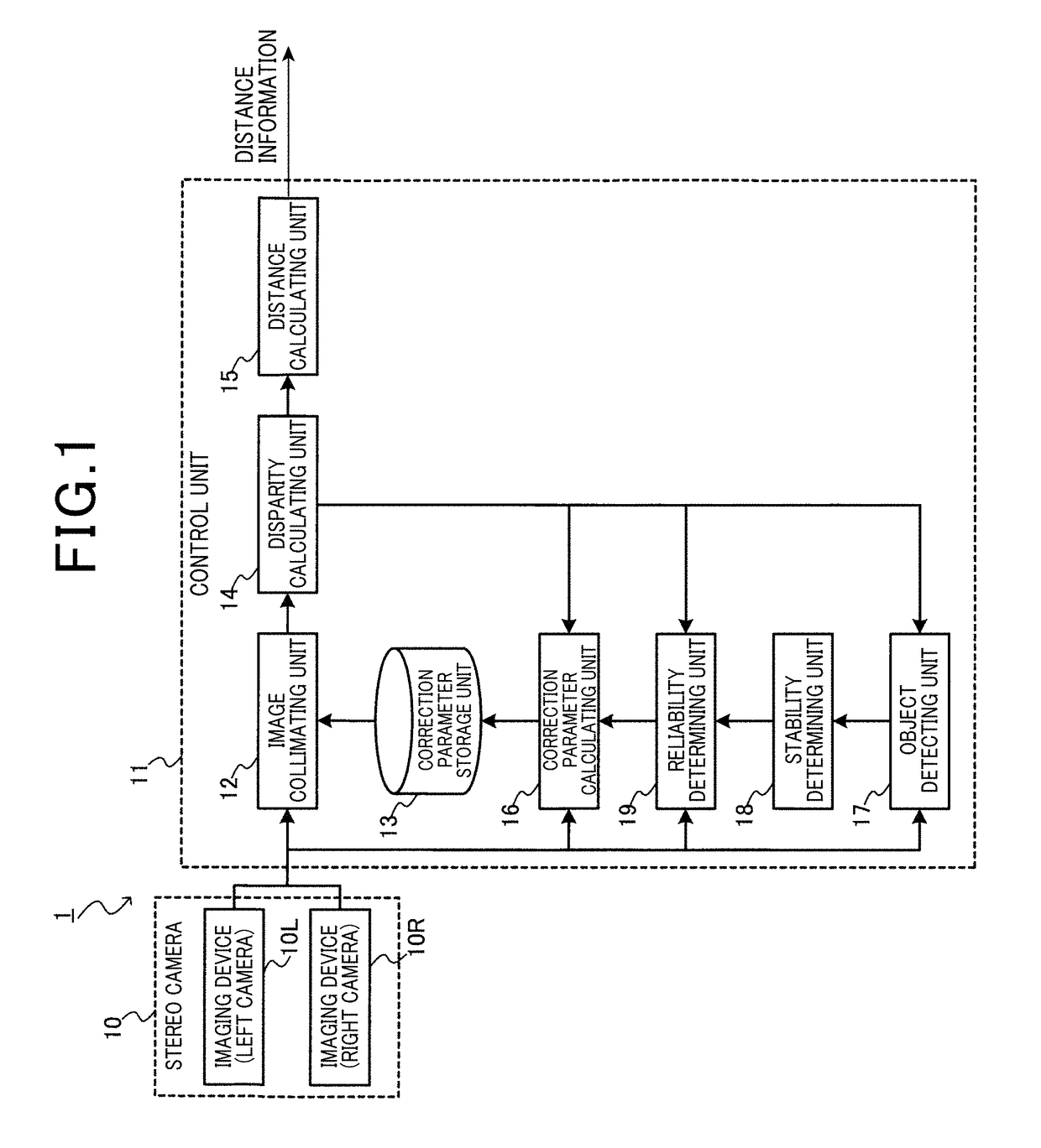
A range correction device includes an image acquiring unit, a collimating unit, a disparity calculating unit, and an updating unit. The image acquiring unit acquires stereo images formed of a plurality of simultaneously captured images. The collimating unit collimates the stereo images acquired by the image acquiring unit, using a correction parameter for correcting a vertical displacement between stereo images. The disparity calculating unit calculates a distribution of horizontal disparities between the stereo images from the stereo images collimated by the collimating unit. The updating unit calculates a distribution of vertical displacements between the stereo images on the basis of the stereo images and the distribution of horizontal disparities calculated by the disparity calculating unit and updates the correction parameter on the basis of the distribution of the calculated vertical displacements.

Description

CROSS-REFERENCE TO RELATED APPLICATION[0001]This application is based on and claims the benefit of priority from earlier Japanese Patent Application No. 2014-128321 filed Jun. 23, 2014, the description of which is incorporated herein by reference.BACKGROUND OF THE INVENTION[0002]Technical Field[0003]The present disclosure relates to a ranging technique. More specifically, the present disclosure relates to a technique that acquires distance information from stereo images captured by a plurality of cameras, more specifically to a technique that corrects vertical displacement between stereo images.[0004]Background Art[0005]Three-dimensional measurement techniques, such as a stereo-matching method, are well known as techniques that acquire distance information from stereo images captured by a plurality of cameras. In the stereo-matching method, stereo matching is performed to search for regions corresponding to each other between the stereo images captured by a plurality of cameras. The...

Claims


Application Information

Patent Timeline
IPC IPC(8): H04N13/00H04N13/02G01C3/06H04N13/239
CPCH04N13/0022G01C3/06H04N2013/0081H04N13/0239H04N13/0271G01C3/10H04N13/243H04N13/246H04N13/239H04N13/128H04N13/271
Inventor ISHIMARU, KAZUHISANIKNEJAD, HOSSEIN TEHRANIMITA, SEIICHILONG, QIAN
Owner DENSO CORP
Learn More