Wearable electronic device

Inactive Publication Date: 2017-07-13
ALTEK CORP
View PDF2 Cites 0 Cited by
  • Summary
  • Abstract
  • Description
  • Claims
  • Application Information

AI Technical Summary

Benefits of technology

The invention describes a wearable electronic device that has two main bodies connected by a wire. The device also has magnetic components on each main body that create a receiving structure for the wire. The wire can be furl into the receiving structure by rotating the main bodies in relation to each other. This eliminates the need for a separate wire receiving device and reduces the size and cost of the wearable electronic device, making it more portable and easy to store.

Problems solved by technology

The wearable electronic devices generally have various connecting wires, and when the wearable electronic devices are to be stored, the connecting wires are often tended to be entangled with each other.
However, by additionally disposing a wire receiving device or structure on the wearable electronic device, the overall volume of the wearable electronic device is increased, thereby lowering a wearability and portability of the wearable electronic device while also increasing a storage space required by the wearable electronic device.
As a result, the overall production cost of the wearable electronic device is also increased.

Method used


Image

  • Wearable electronic device
  • Wearable electronic device
  • Wearable electronic device

Examples


Embodiment Construction

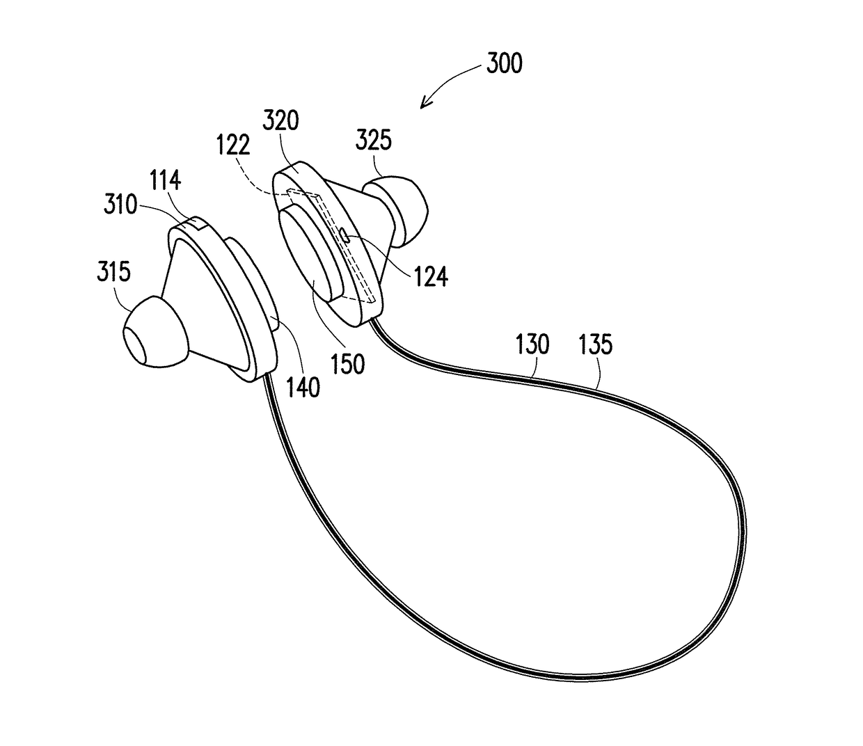
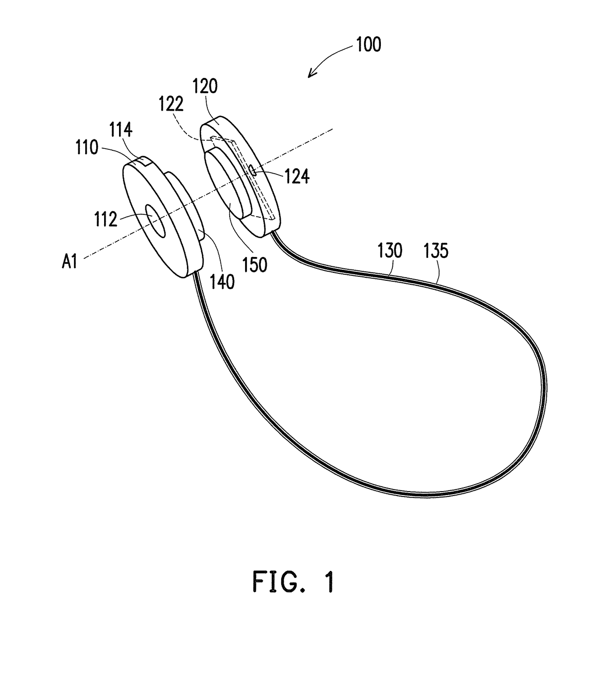
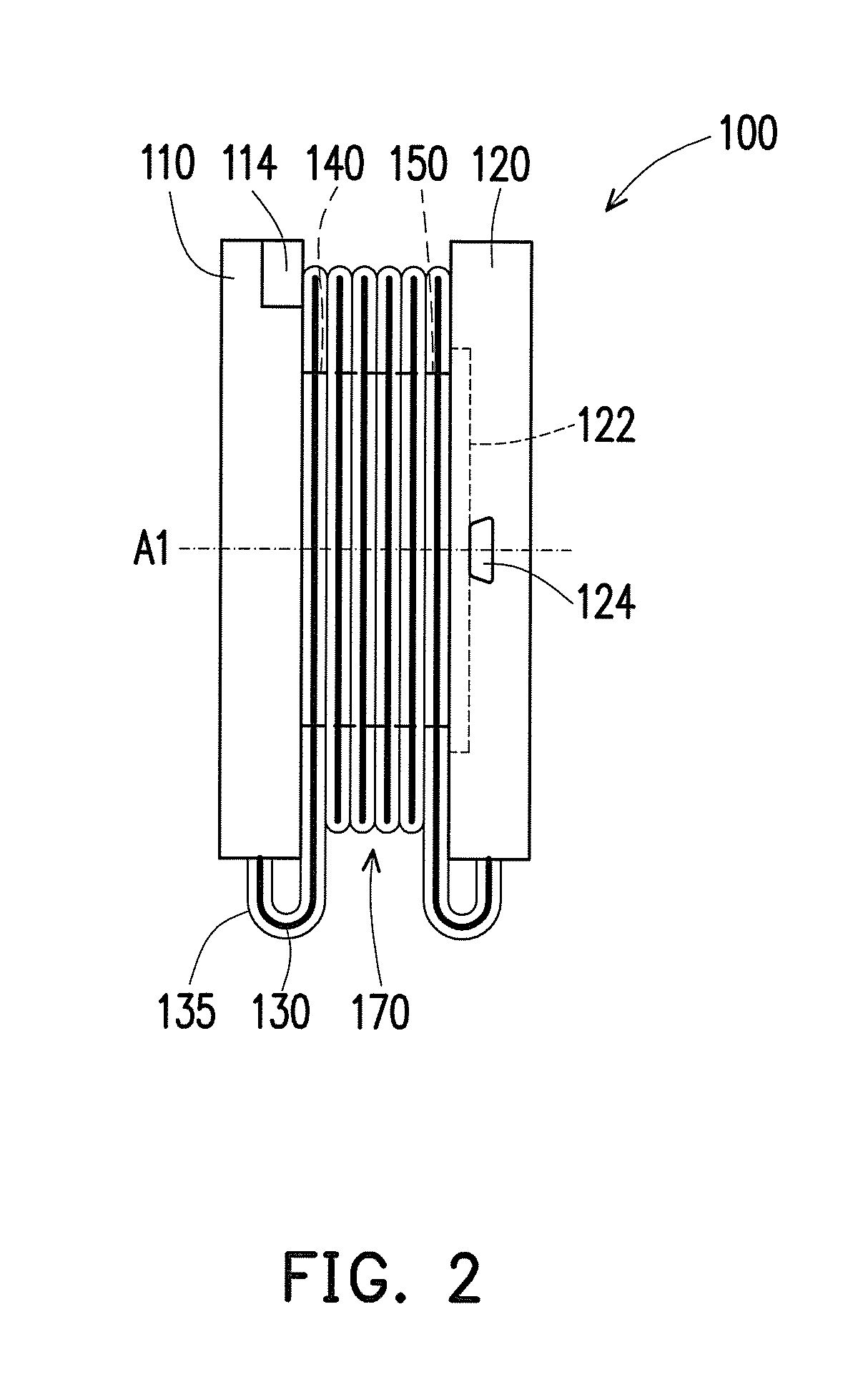
[0025]FIG. 1 is a schematic diagram illustrating a wearable electronic device 100 according to an embodiment of the invention. FIG. 2 is a schematic diagram illustrating an implementation of the wearable electronic device 100 of FIG. 1. Referring to FIG. 1 and FIG. 2, in the present embodiment, the wearable electronic device 100 has a first main body 110, a second main body 120, a wire 130, a first magnetic component 140 and a second magnetic component 150. Two ends of the wire 130 are respectively connected to the first main body 110 and the second main body 120. The first magnetic component 140 is disposed on the first main body 110, and the second magnetic component 150 is disposed on the second main body 120. As shown in FIG. 2, the first magnetic component 140 and the second magnetic component 150 may be magnetically attracted to each other along a direction parallel to an axis A1 so as to form a receiving structure 170 between the first main body 110 and the second main body 1...


PUM


Abstract

A wearable electronic device including a first main body, a second main body, a wire, a first magnetic component and a second magnetic component is provided. The two ends of the wire are respectively connected to the first main body and the second main body. The first magnetic component is disposed on the first main body, and the second magnetic component is disposed on the second main body. The first magnetic component and the second magnetic component are attracted to each other along a direction parallel to an axis, so as to form a receiving structure. The first main body and the second main body rotate in relative to each other along the axis, so as to furl the wire into the receiving structure, and at least one of the first main body and the second main body includes an electronic component.

Description

CROSS-REFERENCE TO RELATED APPLICATION[0001]This application claims the priority benefit of Taiwan application serial no. 105200430, filed on Jan. 13, 2016. The entirety of the above-mentioned patent application is hereby incorporated by reference herein and made a part of this specification.BACKGROUND OF THE INVENTION[0002]1. Field of the Invention[0003]The invention generally relates to a wearable electronic device, and more particularly to, a wearable electronic device having a wire receiving structure.[0004]2. Description of Related Art[0005]As technology industry continue to advances, forms, functionalities and usages of electronic devices become more and more diverse. At the same time, as the electronic devices continue to develop towards a trend of thin and light, the electronic devices become much easier to carry, thereby also accelerating the popularity of the electronic devices. In recent year, in order to further increase the convenience of portable electronic devices, ma...

Claims


Application Information

Patent Timeline
IPC IPC(8): H04R1/10H04R3/00
CPCH04R1/1033H04R3/00H04R1/1016H04R2420/07H04R2420/09
Inventor CHANG, WEI-CHEMAI, CHAO-CHANG
Owner ALTEK CORP
Why Eureka
Try Eureka