
Adjustable Oil Filter Wrench

a wrench and oil filter technology, applied in the direction of wrenches, screwdrivers, manufacturing tools, etc., can solve the problems of limited practical size, difficult to achieve, and limited space for the movement of wrenches to loosen or tighten the oil filter, so as to achieve the effect of loosing the possibility of interference with the surrounding components

Inactive Publication Date: 2017-07-20
MARKOUS EZARIA Y
View PDF7 Cites 0 Cited by
  • Summary
  • Abstract
  • Description
  • Claims
  • Application Information

AI Technical Summary

Benefits of technology

The patent describes a threaded rod with a wrenching feature at one end. This allows for easy adjustment of a screw without interfering with other components. The handle of the rod is designed to extend in a way that only minimal swinging is required to move the adjustment screw in either direction. This improves the efficiency and accuracy of the adjustment process.

Problems solved by technology

Firstly filters are made in many different diameters and secondly space for movement of wrenching tools to loosen or tighten the oil filter is usually quite limited, particularly in a radial directions around the filter.
This requires a tight engagement of the tool with the cylindrical body of the oil filter, often difficult to achieve when the filter is installed on the engine.
There is a limit to how many sizes are practical, resulting in loose or too tight wrenches being used.
Various wrapping tools have been devised which are designed to grip a range of oil filter diameters, but these have required considerable space to be tightened, and may not effectively grip the oil filter if sufficient space is not available.

Method used


Image

  • Adjustable Oil Filter Wrench
  • Adjustable Oil Filter Wrench
  • Adjustable Oil Filter Wrench

Examples


Embodiment Construction

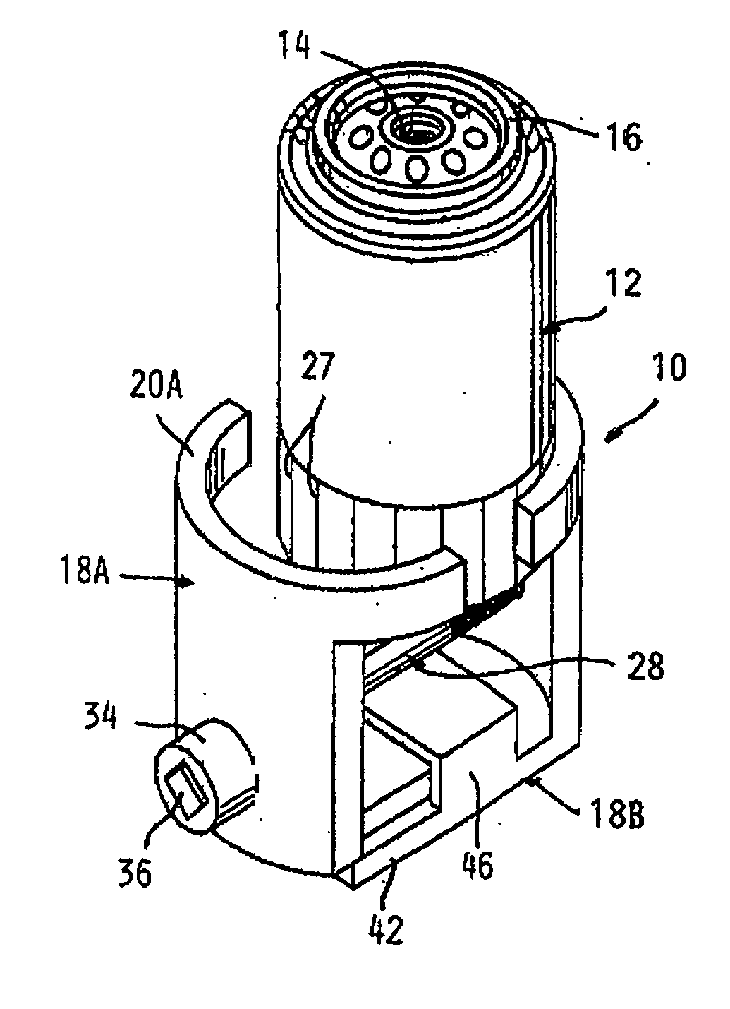
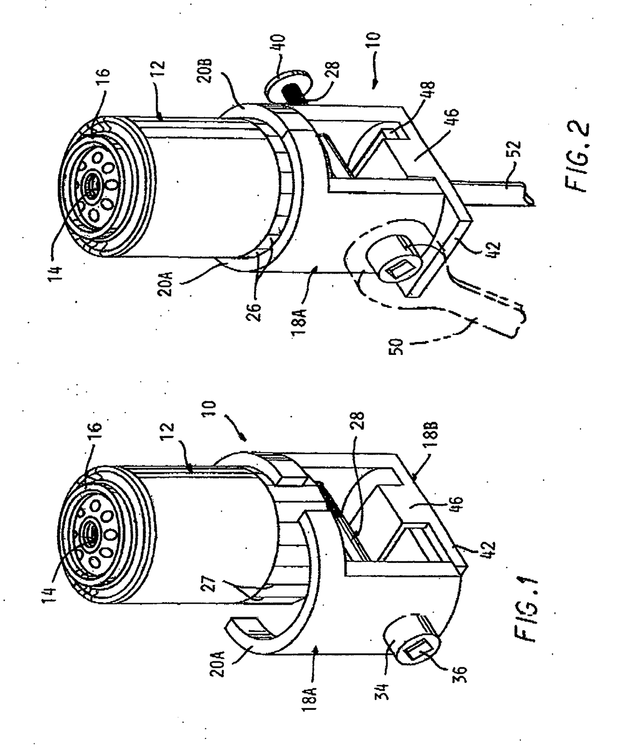
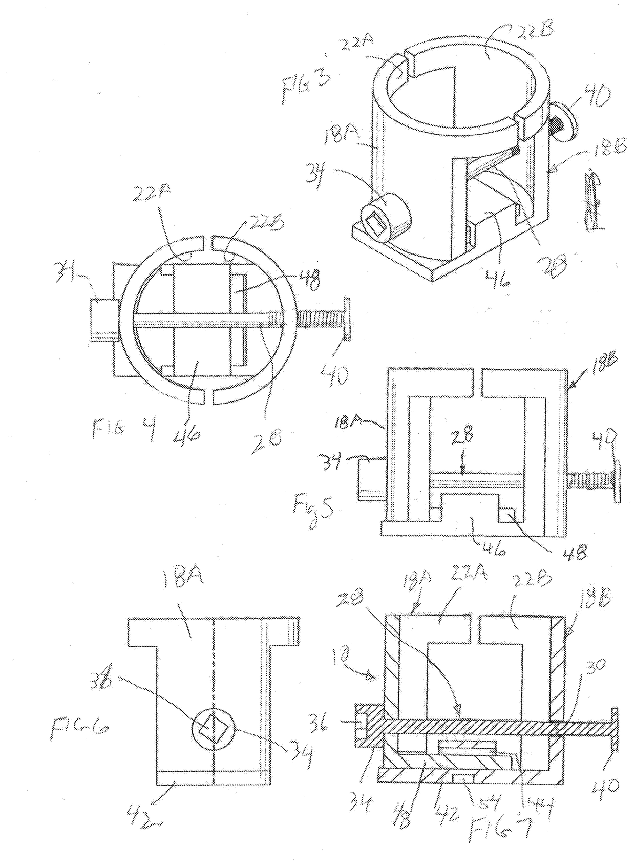
[0025]Referring to the drawings and particularly FIGS. 1 and 2, the oil filter wrench 10 according to the present invention is adapted to grip the bottom end of an automotive oil filter 12 which is installed on a vehicle engine, the wrench able to accommodate oil filters of a size over a substantial range of diameters of the oil filter 12.

[0026]Oil filters 12 are conventionally installed by being threaded onto a threaded tube (not shown) which receives circulation oil flow, received in a threaded hole 14 in the top of the oil filter. A gasket 16 engages a sealing surface (not shown), and is designed to be compressed to a proper degree by advancing of the oil filter on the threaded hole.

[0027]This usually requires more force than is able to be exerted by hand.

[0028]The oil filter wrench 10 according to the present invention is designed to tightly grip oil filters over a range of diameters thereof, and are able to be able to rotate the oil filter to achieve the proper tightness of fit...


PUM


Abstract

An oil filter wrench which has two main parts mounted together so as to be movable towards and away from each other. Each part has an acruate surface aligned with each other. A threaded drive rod has one end in a threaded hole in a side portion of one main part and passes through a clearance hole in a portion of the other main part, with a head engaging the other main part so as to move the parts toward or away from each other to grip or release to the filter. A wrenching feature on the head and of another wrenching feature the bottom of one of the main parts allow a conventional wrenching tool to drive the wrench to rotate the oil filter and to drive the drive element to move the main parts together to grip the filter oil apart to release the same. An extension rod is able to be engaged a wrenching feature on the bottom of said oil filter wrench to loosen or tighten the oil filter on its mounting.

Description

CROSS REFERENCE TO RELATED APPLICATIONS[0001]This invention claims the benefit of U.S. provisional patent application No. 62 / 278,497 filed on Jan. 14, 2016.BACKGROUND OF THE INVENTION[0002]This invention concerns oil filter wrenches adapted to tighten and loosen automotive oil filters, such as oil filters are mounted by being threaded onto a tube which receives circulated oil and are tightened to a specified degree against a sealing surface defined on the engine adjacent the threaded tube. Since oil filters are changed regularly as per the recommendations of the manufacturers, this is a very common maintenance operation and it is desirable that it be able to be carried out quickly and reliably so that no leakage occurs.[0003]A proper degree of tightening is necessary to prevent leakage without damaging the filter, which requires the use of a wrenching tool to tighten the oil filter connection sufficiently and to remove the oil filter when it needs to be changed.[0004]There are two p...

Claims


Application Information

Patent Timeline
Patent Type & Authority Applications(United States)
IPC IPC(8): B25B27/00B25B13/50B25B23/00B25B13/48
CPCB25B27/0042B25B23/0007B25B13/5008B25B13/481B25B13/16
Inventor MARKOUS, EZARIA Y.
Owner MARKOUS EZARIA Y
Learn More