Photoelectric transforming connector for optical fibers

a technology of optical fibers and transformers, applied in the field of photoelectric transforming connectors for optical fibers, can solve the problems of very few possible interferences with other electronic components on the circuit board, and achieve the effect of facilitating the attaching and detaching of the first connection subject and preventing the upsizing of the circuit board

Inactive Publication Date: 2009-04-07
MATSUSHITA ELECTRIC WORKS LTD
View PDF11 Cites 10 Cited by
  • Summary
  • Abstract
  • Description
  • Claims
  • Application Information

AI Technical Summary

Benefits of technology

[0007]According to such a constitution, under a state that the second connection subject (equivalent to a socket) is attached to the shell, the first connection subject (equivalent to a plug) and the second connection subject can be aligned contiguously by attaching the first connection subject in a direction perpendicular to the bottom plate of the shell. Therefore, works for attaching and detaching the first connection subject becomes easier, and this photoelectric transforming connector can be incorporated in an electronic apparatus without upsizing the height of the electronic apparatus. In addition, when this photoelectric transforming connector is implemented on a circuit board, the first connection subject can be attached to and detached from the bottom plate of the shell in a direction perpendicular thereto, so that a possibility to interfere with other electronic components on the circuit board becomes very few. Thus, a space for enabling attaching and detaching works of the first connection subject easier can be miniaturized, so that upsizing of the circuit board can be prevented. As a result, the photoelectric transforming connector can be applied to the miniaturized mobile apparatus.

Problems solved by technology

In addition, when this photoelectric transforming connector is implemented on a circuit board, the first connection subject can be attached to and detached from the bottom plate of the shell in a direction perpendicular thereto, so that a possibility to interfere with other electronic components on the circuit board becomes very few.

Method used


Image

  • Photoelectric transforming connector for optical fibers
  • Photoelectric transforming connector for optical fibers
  • Photoelectric transforming connector for optical fibers

Examples


first embodiment

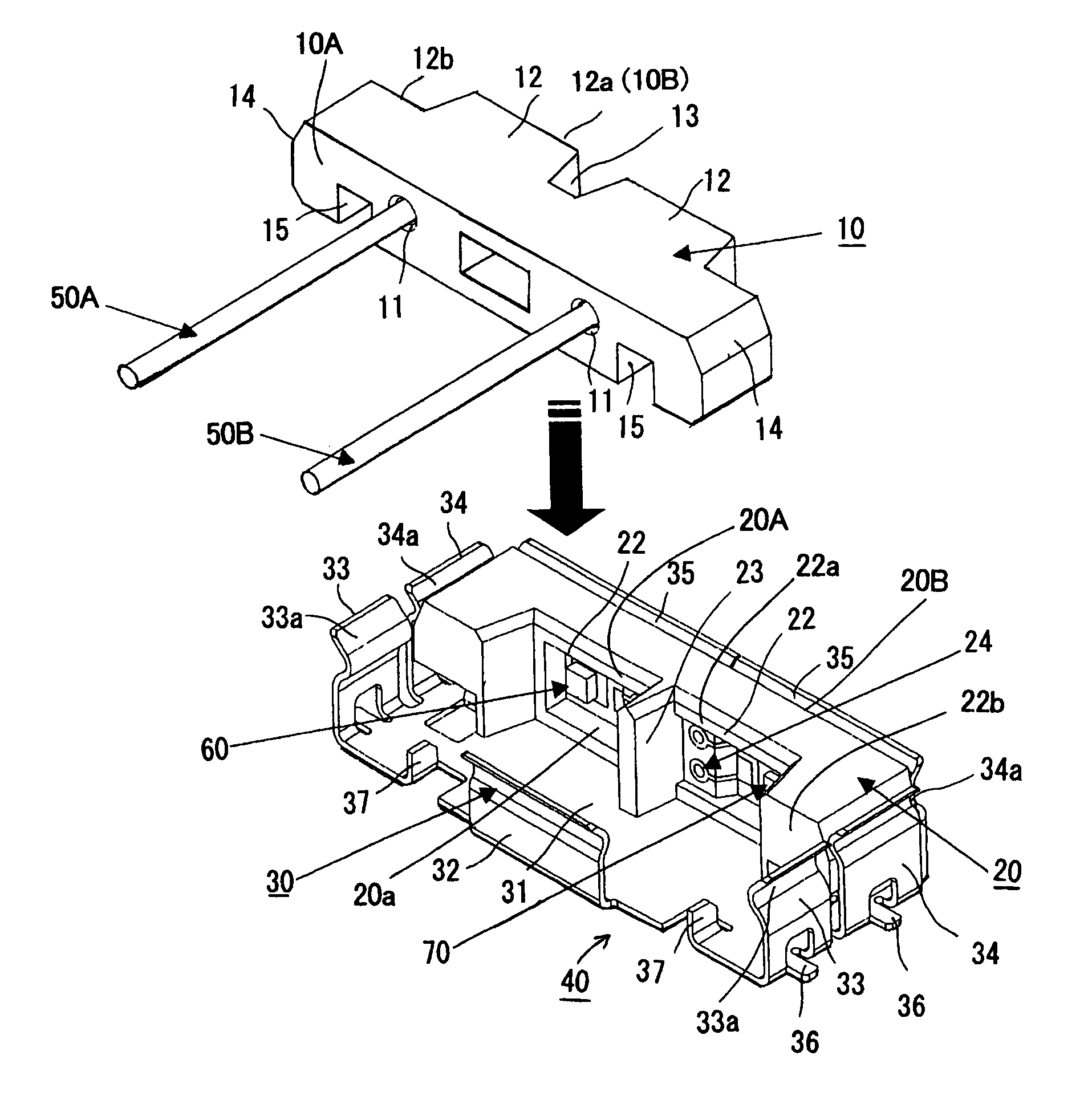
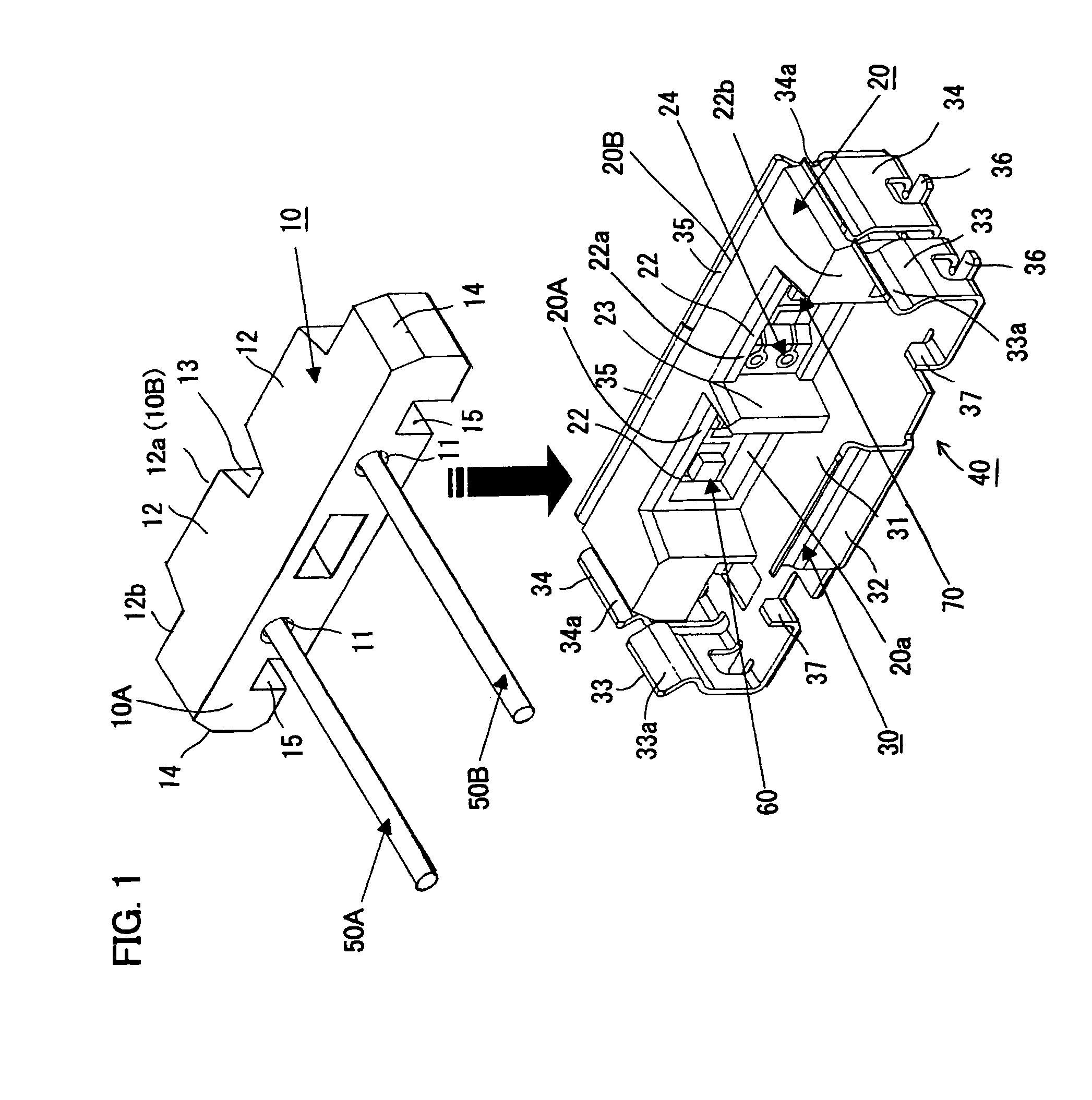
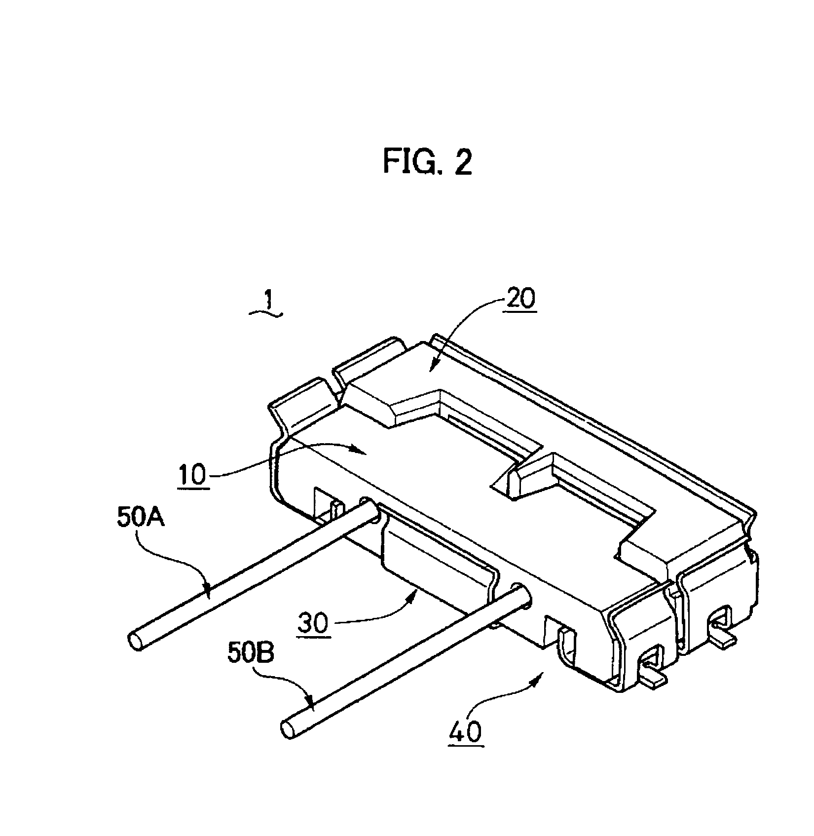
[0029]A photoelectric transforming connector for optical fibers in accordance with a first embodiment of the present invention is described with reference to drawings. FIG. 1 shows a state before connecting a plug 10 (first connection subject) with an MID (Molded Interconnect Device) 20 (second connection subject) comprising a three dimensional circuit board, which constitute the photoelectric transforming connector 1 in accordance with the first embodiment. FIG. 2 and FIGS. 3A to 3D show the photoelectric transforming connector 1 after connecting the plug 10 with the MID 20. FIG. 4 shows a state to fix optical fibers in the MID. FIG. 5 is a view of the photoelectric transforming connector 1 in the same state as that in FIG. 1 observed from a bottom face side. FIGS. 9 to 12 respectively show a structure of each portion of the photoelectric transforming connector 1.

[0030]The photoelectric transforming connector 1 comprises the plug 10 to which optical fibers are connected, the MID 20...

second embodiment

[0051]A photoelectric transforming connector for optical fibers in accordance with a second embodiment of the present invention is described with reference to the drawings. The above mentioned first embodiment relates to the photoelectric transforming connector in which two optical fibers are connected to the plug so that the transmission and receiving of the light signals can be performed simultaneously. The second embodiment relates to a photoelectric transforming connector in which only one optical fiber is connected to the plug so that only the transmission or receiving of the light signal can be performed. Elements which are common in the first embodiment are designated by the same numeral, so that the descriptions of them are omitted.

[0052]FIG. 14 shows a state before connecting a plug 110 (first connection subject) to an MID (Molded Interconnect Device) 120 (second connection subject) comprising three-dimensional circuit board, which constitute the photoelectric transforming ...


PUM


Abstract

A photoelectric transforming connector for optical fibers capable of application to a compact mobile apparatus such as a mobile phone comprises: a plug having a first light emitting portion for transmitting a light signal and / or a first light receiving portion for receiving a light signal through an optical fiber; an MID having a second light receiving portion facing the first light emitting portion and transforming the light signal from the first light emitting portion to an electric signal and / or a second light emitting portion facing the first light receiving portion and transforming an electric signal to a light signal and transmitting it to the first light receiving portion; and a shell to which the plug and the MID are attached. The shell has a bottom plate to which the plug and the MID are attached in a manner so that the first light emitting portion faces the second light receiving portion and / or the first light receiving portion faces the second light emitting portion, and a plurality of elastic pieces provided for standing up toward top face side from four side of the bottom plate and contacting the plug and the MID. Thereby, the plug can be attached to and detached from the bottom plate of the shell in a vertical direction.

Description

TECHNICAL FIELD[0001]The present invention relates to a photoelectric transforming connector for optical fibers that transforms a light signal to an electric signal or an electric signal to a light signal.BACKGROUND ART[0002]In such a photoelectric transforming connector, as described in, for example, Japanese Laid-Open Patent Publication No. 11-214100, a plug is generally connected to a socket in frontally direction when the socket and the plug constituting a connector is coupled (lateral connection).[0003]According to such a method for connecting the plug to the socket in frontally direction, optical axes of the socket and the plug can be performed precisely. However, when it is assumed that the photoelectric transforming connector is disposed inside a compact electronic apparatus such as a mobile phone or an electronic personal organizer, connection work of the socket and the plug becomes extremely difficult because various electronic members are mounted on a circuit board to whi...

Claims


Application Information

Patent Timeline
Patent Type & Authority Patents(United States)
IPC IPC(8): G02B6/36G02B6/42
CPCG02B6/4292G02B6/4246
Inventor HARANO, TOMOKAZUIIDA, MITSURUSHIMAYA, KENICHIKAMBE, YOSHIAKI
Owner MATSUSHITA ELECTRIC WORKS LTD
Why Eureka
Try Eureka